Z8 Microcontrollers
Instruction Descriptions and Formats ZiLOG
12-24 UM001601-0803
DA
DECIMAL ADJUST
DA
Decimal Adjust
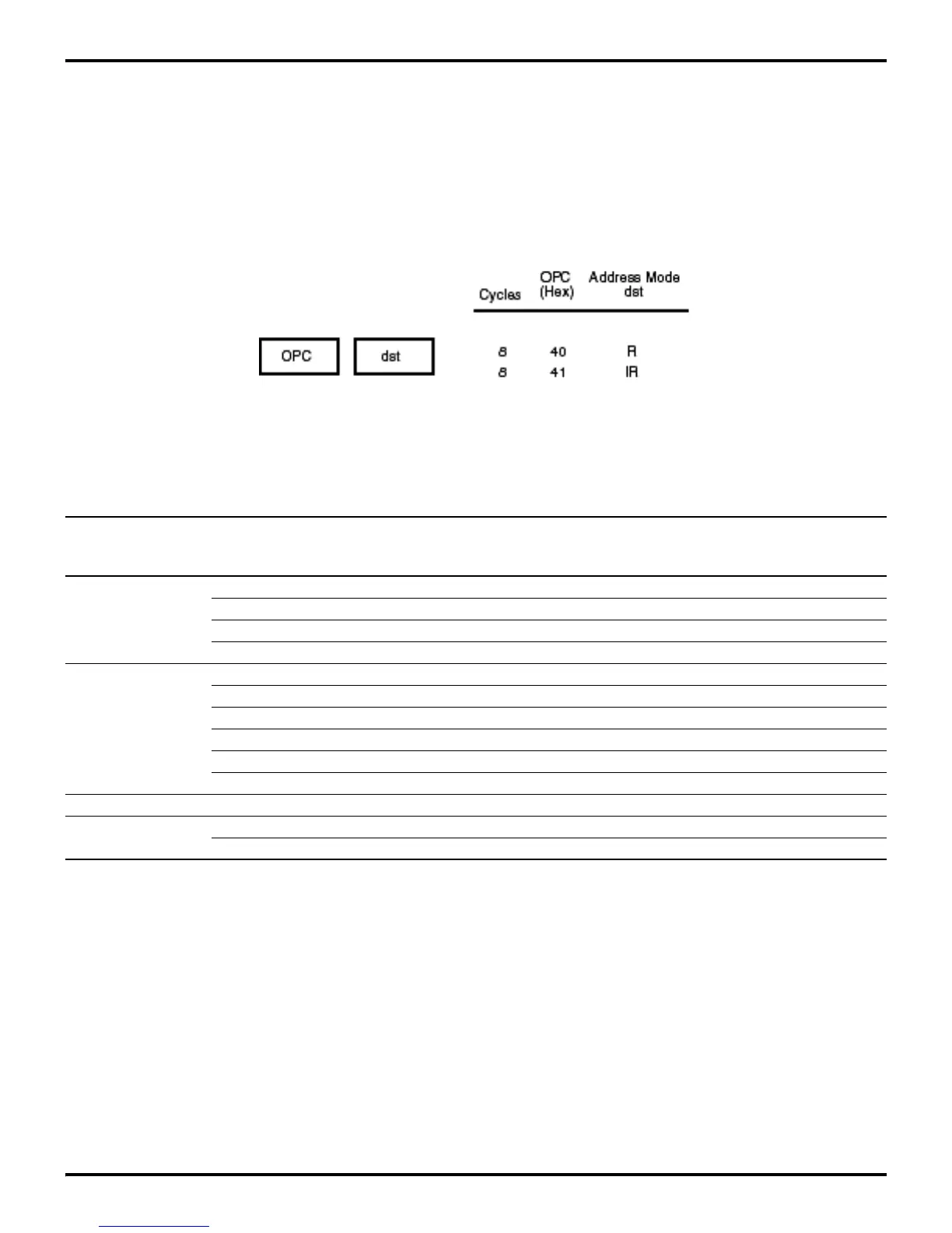
DA dst
Instruction Format:
Operation:
dst <— DA dst
The destination operand is adjusted to form two 4-bit BCD digits following a binary addition or subtraction
operation on BCD encoded bytes. For addition (ADD and ADC) or subtraction (SUB and SBC), the following table
indicates the operation performed.
If the destination operand is not the result of a valid addition or subtraction of BCD digits, the operation is
undefined.
Note:
Address modes R or IR can be used to specify a 4-bit Working Register. In this format, the destination Working
Register operand is specified by adding 1110B (EH) to the high nibble of the operand. For example, if Working
Register R12 (CH) is the destination operand, then ECH will be used as the destination operand in the Op Code.
Carry Bits 7-4 H Flag Bits 3-0 Number Carry
Instruction Before Val ue Before Value Added To After
DA (HEX) DA (HEX) Byte DA
0 0-9 0 0-9 00 0
0 0-8 0 A-F 06 0
0 0-9 1 0-3 06 0
ADD 0 A-F 0 0-9 60 1
ADC 0 9-F 0 A-F 66 1
0 A-F 1 0-3 66 1
1 0-2 0 0-9 60 1
1 0-2 0 A-F 66 1
1 0-3 1 0-3 66 1
0 0-9 0 0-9 00 0
SUB 0 0-8 1 6-F FA 0
SBC 1 7-F 0 0-9 A0 1
1 6-F 1 6-F 9A 1
Flags: C: Set if there is a carry from the most significant bit; cleared otherwise (see table above).
Z: Set if the result is zero; cleared otherwise.
S: Set if result bit 7 is set (negative); cleared otherwise.
D Unaffected
H: Unaffected
 Loading...

