30 Operation principle and hardware description
Operation principle
The ACL30 elevator drive is a wall or cabinet mountable drive for controlling an
asynchronous motor or a permanent magnet motor. The following components define
the operation of the drive. See the main circuit on page 30.
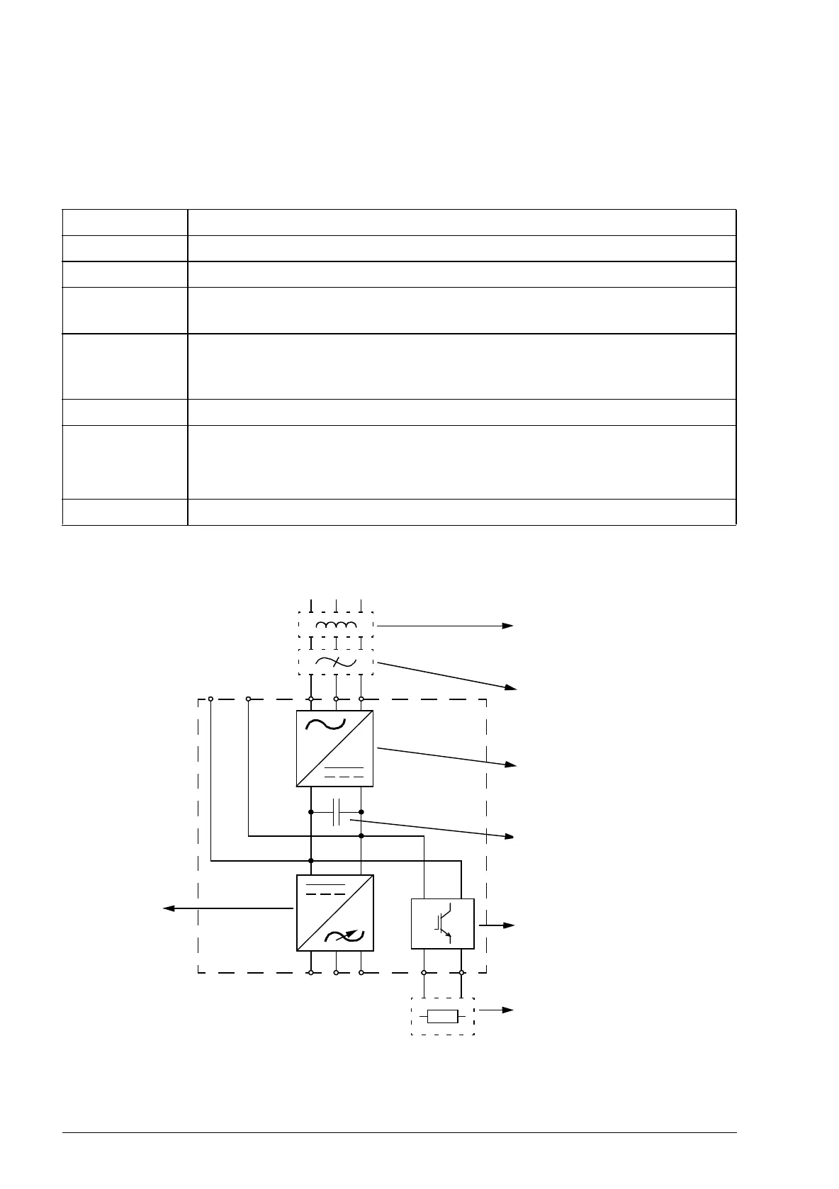
Main circuit
Component Description
Rectifier Converts the three-phase AC voltage to DC voltage.
Capacitor bank Stores energy which stabilizes the intermediate circuit DC voltage.
Drive Converts DC voltage to AC voltage and vice versa. The motor is controlled
by switching the IGBTs of the drive.
Brake chopper Conducts the energy generated by a decelerating motor from the DC bus to
a braking resistor. The brake chopper is built in the ACL30. Brake resistors
are external options.
Brake resistor Dissipates the regenerative energy by converting it to heat.
Mains choke Reduces
• harmonics and r.m.s in the input current
• supply disturbance and low-frequency interference.
Mains filter See page 339.
Motor output
Brake chopper (see chapter
Resistor braking on
page 343)
+–
UDC+ UDC– V1 W1U1
V2 W2U2 R– R+
AC supply
ACL30
Drive
Capacitor bank
Rectifier
CHK-xx mains choke (see
chapter Mains chokes on
page 335)
JFI-xx EMC filter (see chapter
EMC filters on page 339)
JBR-xx brake resistor (see
chapter Resistor braking on
page 343)