344 Resistor braking
Selecting a brake resistor
To select a brake resistor, calculate the following:
• maximum power generated by the motor during braking
• continuous power based on the braking duty cycle
• braking energy during the duty cycle.
Pre-selected resistors are available from ABB as shown in the Brake resistor
selection table below. If the listed resistor is not sufficient for the application, a custom
resistor can be selected within the limits imposed by the internal brake chopper of the
ACL30 drive, based on the following rules.
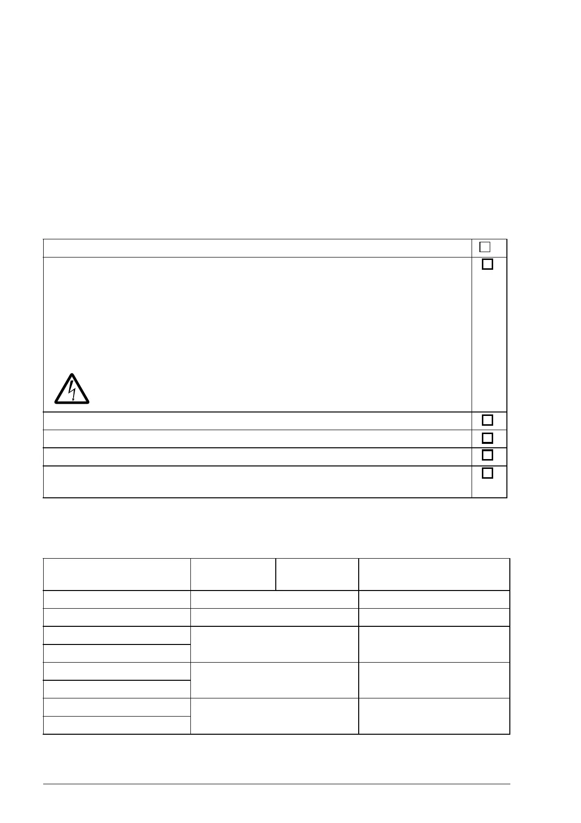
Brake resistor selection table
The ratings apply at an ambient temperature of 40 °C (104 °F).
Apply the following rules:
Check the resistance of the custom resistor is at least R
min
.
You can calculate the braking power capacity with different resistance values using the
following formula:
where, U
DC
= 840 V.
WARNING! Never use a brake resistor with a resistance below the value
specified for the particular drive type. The drive and the chopper cannot
handle the overcurrent caused by the low resistance.
Make sure the maximum braking power does not exceed P
brmax
at any point.
Limit the average braking power within P
brcont
.
Do not exceed the braking energy dissipation capacity of the selected resistor.
Protect the resistor from thermal overload. See Contactor protection of drive on
page 345.
Drive type
ACL30-04...
Frame size R
min
(ohm)
Type
-06A0 B 120 JBR-01
-09A0 B 80 JBR-03
-013A B 40 JBR-04
-017A
-023A C 20 JBR-05
-030A
-050A D 13 JBR-06
-070A
R
min
– The minimum allowed resistance of the braking resistor.