MODULE 1: SYSTEM TOUR
1-16 AEROSET
®
Customer Training Guide
94858-103 — July 2003
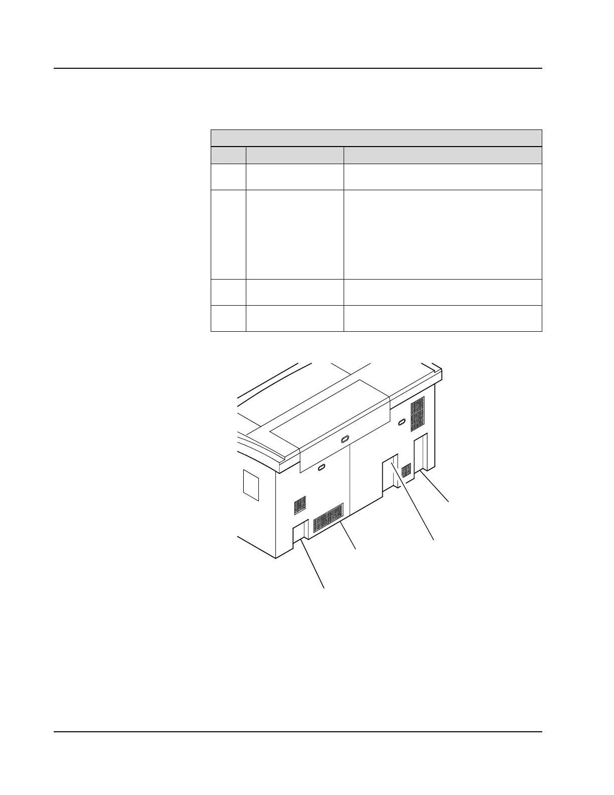
Figure 1.9: Rear View of the AEROSET Analyzer
Rear of Analyzer
Item Component Description
1
Main Circuit Breaker
Switch
Turns the power ON/OFF for the entire
System.
2
Water Supply and
Drainage Tubing
Incoming Deionized Water supply and
drainage tubing for the water bath,
Low-Concentration Waste, overflow, and
refrigerator. Also includes the
High-Concentration Waste tubing which can be
attached to a separate Waste Container.
The serial number is located above this area.
3
Refrigerator
Condensation Pan
Captures condensation from the reagent
refrigeration units.
4
GPIB Connector Transmits all communications between the
SCC and the Analyzer.
• Point out location of the instrument
serial number. Customer instruments
will have a plate attached to the left-
rear of the instrument above the
water supply/drainage panel, and also
on TSB sticker located in front,
behind front-left door.
2-Water Supply/
Drainage Panel
125671
3-Refrigerator
Condensation
Pan
1-Main
Circuit Breaker
4-GPIB
Connector