DD+DIS150.06E
Repair and Service
Replacements / Repair Procedures
DOCUMENT CONTROL NOTE:
The controlled version of this document resides on MedNet. Any printed copy of this document is uncontrolled.
Edition 1, Revision 2 CR 30-X Chapter 3.5 / 62
03-2009 Type 5175 / 100/110 Agfa Company Confidential
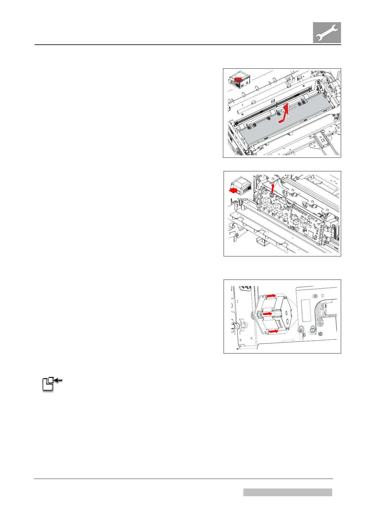
(16) Slide IP guide plate to the left and lift it out.
Figure 150
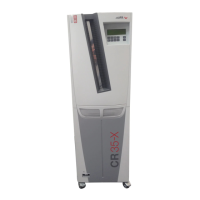
(17) Remove cable at plug P29 of IP handling
board.
(18) Open cable holders.
Figure 151
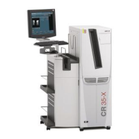
(19) Remove 4 screws of stepper motor roller
clamping (only 3 screws are shown in
Figure 152).
(20) Remo
ve motor.
Figure 152
ASSEMBLY:
(1) Mount in reverse order. Observe IMPORTANT note below:


 To Next Page