DD+DIS150.06E
Repair and Service
Replacements / Repair Procedures
DOCUMENT CONTROL NOTE:
The controlled version of this document resides on MedNet. Any printed copy of this document is uncontrolled.
Edition 1, Revision 2 CR 30-X Chapter 3.5 / 104
03-2009 Type 5175 / 100/110 Agfa Company Confidential
(2) When finished with re-mounting, continue with:
• Basic Protective Earth Test. See section 4.3.1.
• Electrical Check according to National Regulations. See section 4.3.2.
•
Verification of the successful power supply replacement. See section 4.3.3.
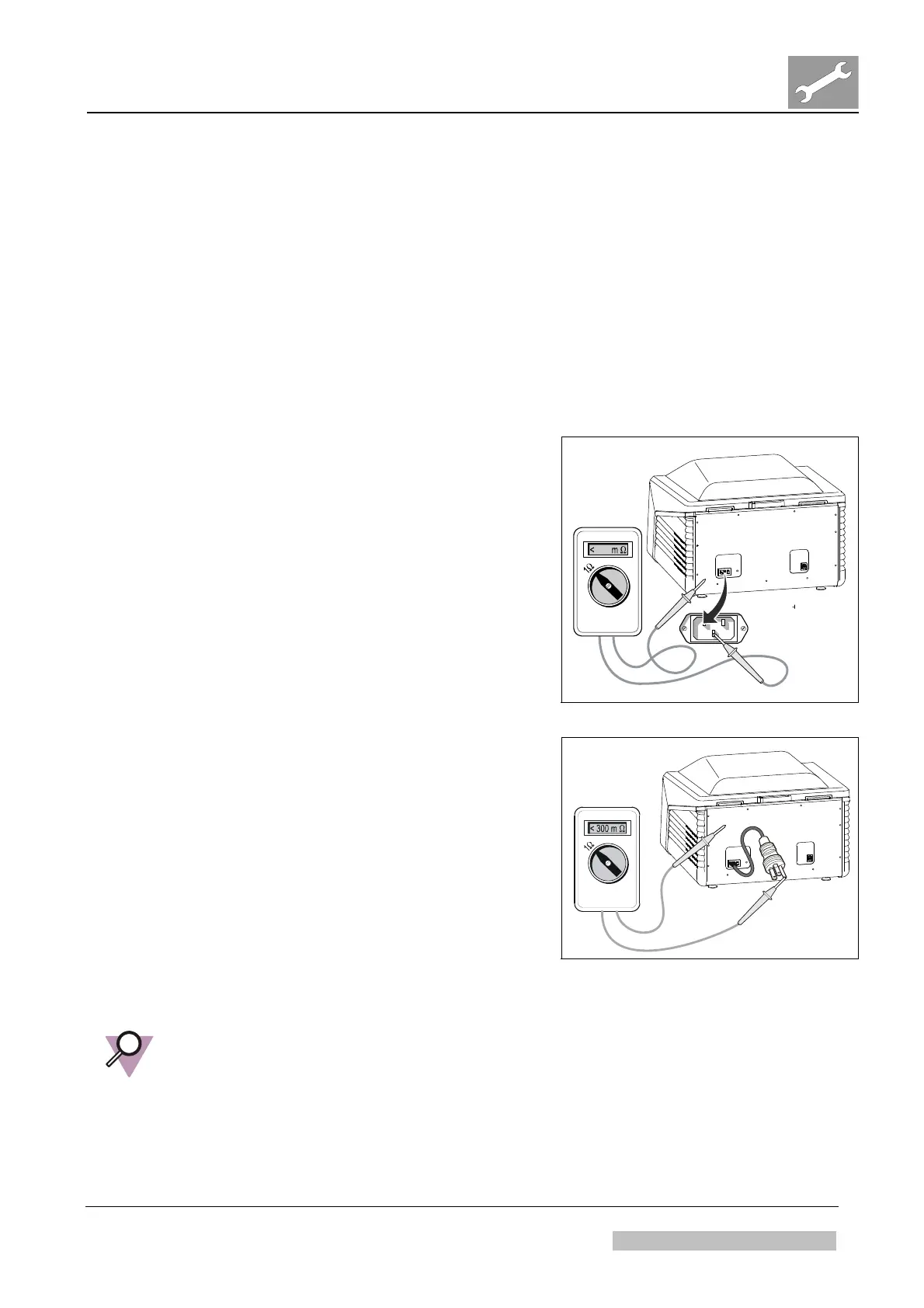
4.3.1 Basic Protective Earth Test
(1)
Use a multimeter that is capable to
measure a resistance < 1 Ohm.
(2) Put one probe at the ground connector of
the mains input.
(3) Put the other probe at a few metallic parts,
the customer could touch.
The electrical resistance has to be ≤ 0.2
Ohm.
Refer to Figure 252.
517511ai.cdr
200
Figure 252
517509ah.cdr
(4) Insert the power cord at the digitizer side;
leave it disconnected at the wall side.
(5) Put one probe at the ground connector of
the mains connector.
(6) Put the other probe at a few metallic parts,
the customer could touch.
The electrical resistance in this case has
to be ≤ 0.3 Ohm.
Refer to Figure 253.
Figure 253
IMPORTANT:
In case the electrical resistance of one measurement exceeds the limits (0.2 Ohm
without mains cable; 0.3 Ohm with mains cable) check the digitizer for loose grounding
connections!
 Loading...