4 Triggering
118 InfiniiVision Oscilloscopes User’s Guide
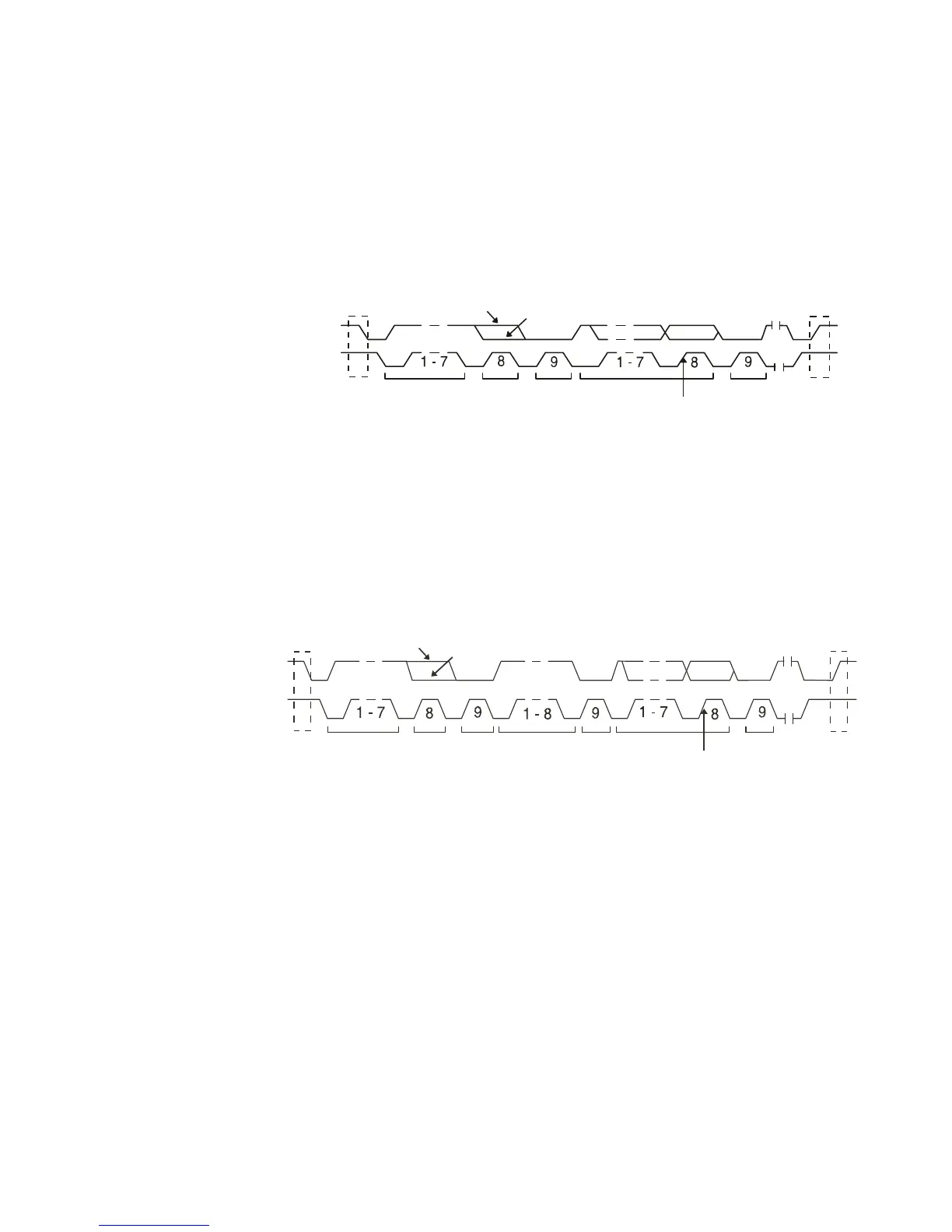
• Frame (Start: Addr7: Read: Ack: Data) or Frame (Start: Addr7: Write: Ack: Data)
— The oscilloscope triggers on a read or write frame in 7-bit addressing mode on
the 17th clock edge if all bits in the pattern match. For triggering purposes, a restart
is treated as a start condition.
• Frame (Start: Addr7: Read: Ack: Data: Ack: Data2) or Frame (Start: Addr7: Write:
Ack: Data: Ack: Data2) — The oscilloscope triggers on a read or write frame in
7-bit addressing mode on the 26th clock edge if all bits in the pattern match. For
triggering purposes, a restart is treated as a start condition.
• 10-bit Write — The oscilloscope triggers on a 10-bit write frame on the 26th clock
edge if all bits in the pattern match. The frame is in the format:
Frame (Start: Address byte 1: Write: Address byte 2: Ack: Data)
Start or
Restart
Condition
Trigger point
17th clock edge
Address
Read
Write
R/
Ack
Data
Ack
Stop
Condition
SCL
SDA
Stop
Condition
Trigger point
26th clock edge
Ack
Ack
Ack
Start
Condition
Address
R/W Data
Data 2
Read
Write

 Loading...


