4 Triggering
128 InfiniiVision Oscilloscopes User’s Guide
LIN Trigger
LIN (Local Interconnect Network) trigger setup consists of connecting the oscilloscope to
a serial LIN signal.
LIN triggering will trigger on the rising edge at the Sync Break exit of the LIN single-wire
bus signal that marks the beginning of the message frame. If the N5424A CAN/LIN
Automotive Triggering and Decode option is installed on your oscilloscope, the Frame ID
and Frame ID and Data trigger types are also available.
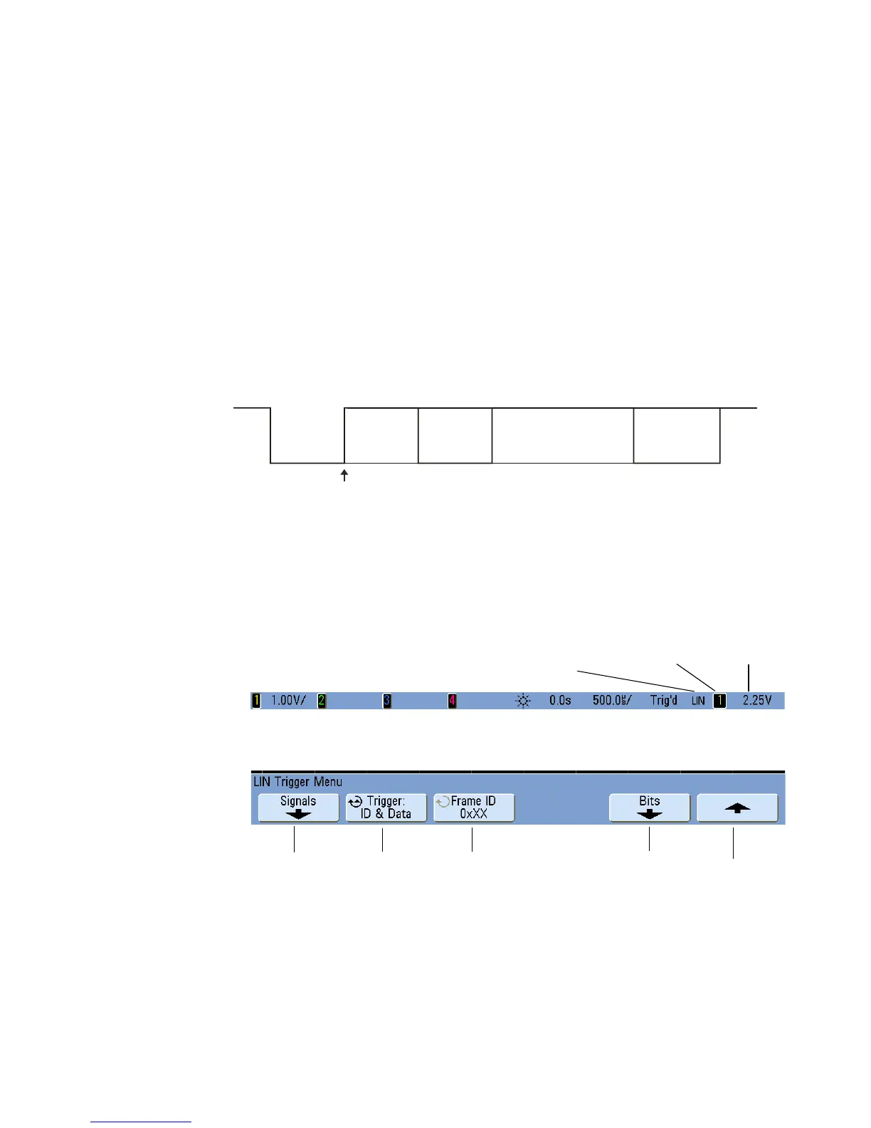
A LIN signal message frame is shown below:
1 Press [Save/Recall]&Default Setup.
2 Turn on the analog or digital channel that you will be using for the LIN signal.
3 Press the [More] key in the Trigger section of the front panel, and rotate the Entry
knob until LIN is displayed in the Trigger softkey.
4 Press the Settings softkey to display the LIN Trigger Menu.
Sync Break Exit
Sync
Break
Sync
Field
Identifier
Break
Data
Fields
Checksum
Field
Trigger level
or threshold
Currently selected
signal source
LIN trigger
Trigger
condition
Signals
menu
Return to
previous menu
Select
Frame ID
Enter data
values
 Loading...


