10 Serial Decode/Lister
308 InfiniiVision Oscilloscopes User’s Guide
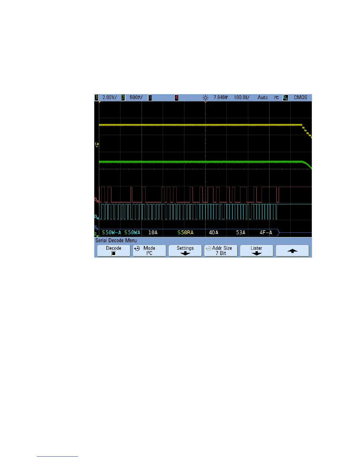
Interpreting I
2
C Decode
• Angled waveforms show an active bus (inside a packet/frame).
• Mid-level blue lines show an idle bus.
• In the decoded hexadecimal data:
• Address values appear at the start of a frame.
• Write addresses appear in light-blue along with the “W” character.
• Read addresses appear in yellow along with the “R” character.
• Restart addresses appear in green along with the “S” character.
• Data values appear in white.
• “A” indicates Ack (low), “~A” indicates No Ack (high).
• Decoded text is truncated at the end of the associated frame when there is
insufficient space within frame boundaries.
• Red dots in the decode line indicate that more data can be displayed. Scroll or expand
the horizontal scale to view the data.
 Loading...


