Triggering 4
InfiniiVision Oscilloscopes User’s Guide 131
MIL-STD 1553 Setup and Triggering
The N5469A MIL-STD 1553 triggering and decode option (Option 553) requires a
four-channel InfiniiVision Series oscilloscope.
The MIL-STD 1553 triggering and decode solution supports bi-phase MIL-STD 1553
signaling. the standard 1553 Manchester II encoding, data rate of 1 Mb/s, and word
length of 20 bits.
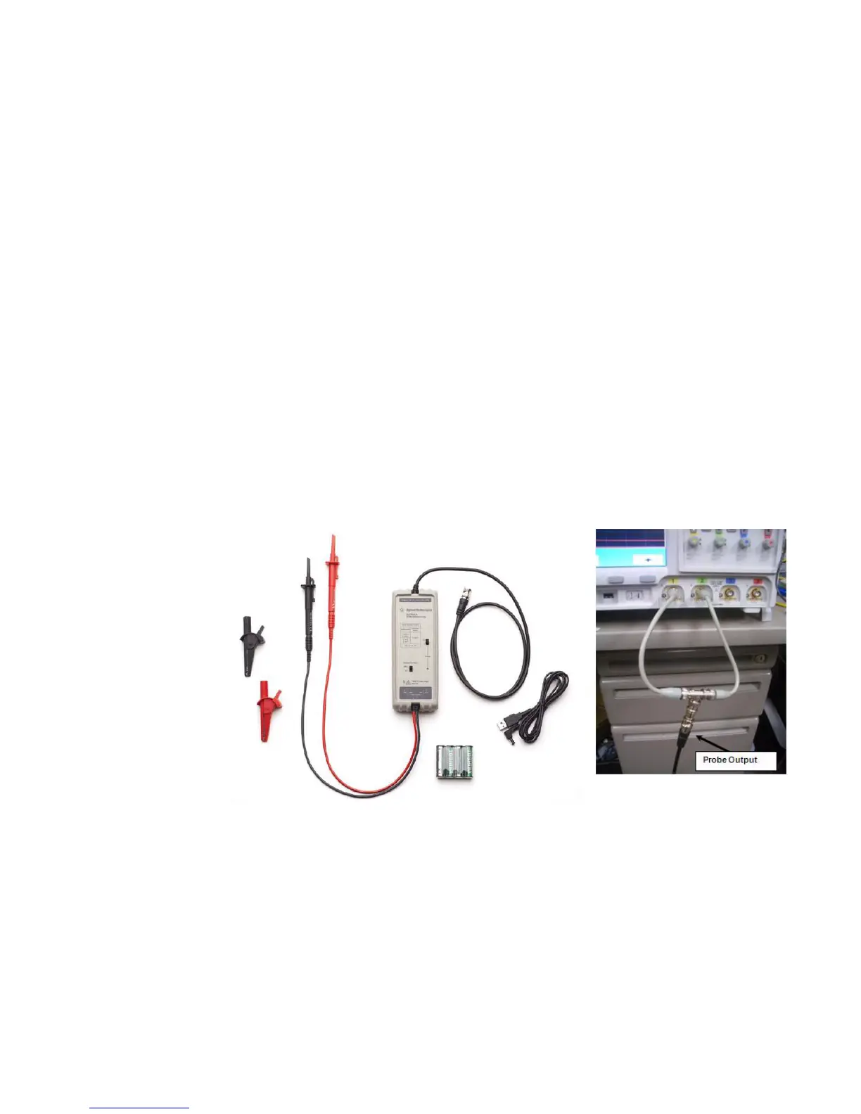
Probing MIL-STD 1553 Signals
The MIL-STD 1553 differential bus must be probed with a differential active probe.
Agilent recommends the N2791A 25 MHz differential active probe.
Output of the differential probe must be fed, via a BNC tee and two equal-length BNC
cables, into two channels of the oscilloscope. This way, the oscilloscope can perform
dual threshold triggering (using upper and lower thresholds).
This N2791A differential probe works well because it is designed for 1 MOhm impedance
oscilloscope inputs.
If you use a different differential probe that is designed for 50 Ohm impedance
oscilloscope inputs, be sure to set only one of the oscilloscope channel input impedances
to 50 Ohms (because the two input channel’s impedances are seen in parallel).

 Loading...


