Triggering 4
InfiniiVision Oscilloscopes User’s Guide 115
I
2
C Trigger
An I
2
C (Inter-IC bus) trigger setup consists of connecting the oscilloscope to the serial
data (SDA) line and the serial clock (SCL) line, then triggering on a stop/start condition, a
restart, a missing acknowledge, an EEPROM data read, or on a read/write frame with a
specific device address and data value.
1 Press [Save/Recall]&Default Setup.
2 Press the [Label] key to switch labels on.
3 Turn on any analog or digital channels that you will be using for the I
2
C signals.
4 Press the [More] key in the Trigger section of the front panel, rotate the Entry knob
until I
2
C is displayed in the Trigger softkey, then press the Settings softkey to display
the I
2
C Trigger Menu.
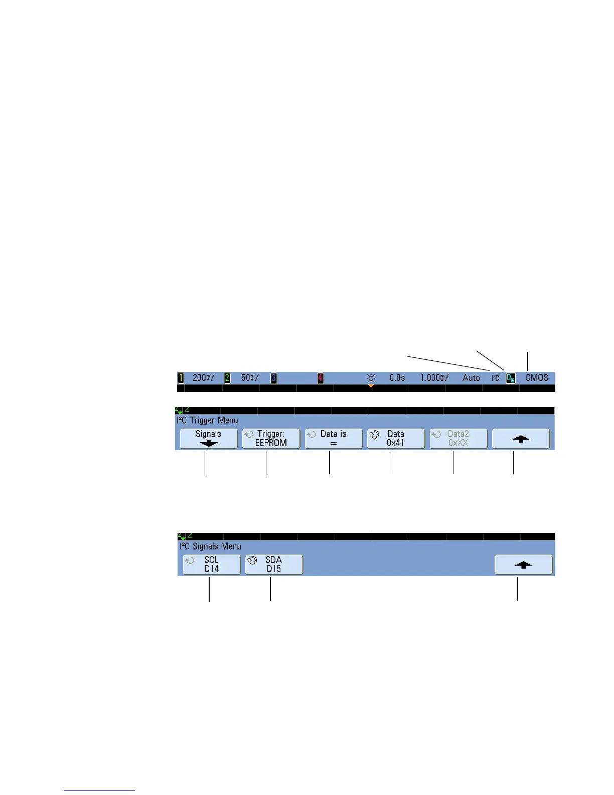
5 Press the Signals softkey to display the I
2
C Signals Menu.
6 Connect an oscilloscope channel to the SCL (serial clock) line in the device under test,
then set the SCL clock channel softkey to that channel.
Signals
menu
Trigger on:
condition
Address
Data 2
value
Trigger level
or threshold
Currently selected Clock
or Data channel
I
2
C trigger
Return to
previous menu
Data
value
SCL Clock
channel
SDA Data
channel
Return to
previous menu
 Loading...


