10 Serial Decode/Lister
334 InfiniiVision Oscilloscopes User’s Guide
• A parity error will cause the associated data word to be shown in red, which includes
the 5-8 data bits and the optional 9th bit.
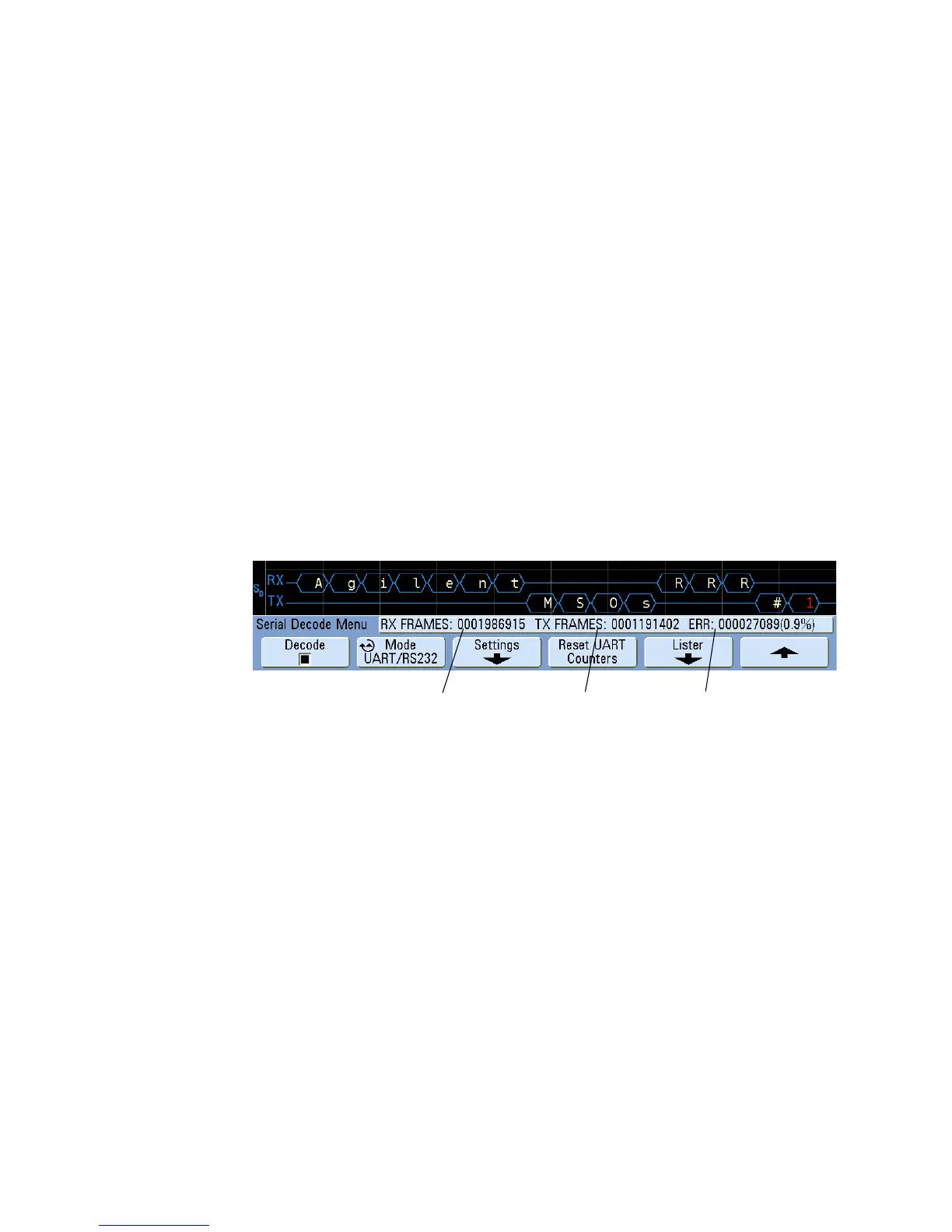
UART/RS232 Totalizer
The UART/RS232 totalizer consists of counters that provide a direct measure of bus
quality and efficiency. The totalizer appears on screen whenever UART/RS232 Decode is
ON in the Serial Decode Menu.
The totalizer is running, counting frames and calculating the percentage of error frames,
even when the oscilloscope is stopped (not acquiring data).
The ERR (error) counter is a count of Rx and Tx frames with parity errors. The TX FRAMES
and RX FRAMES counts include both normal frames and frames with parity errors. When
an overflow condition occurs, the counter displays OVERFLOW.
The counters can be reset to zero by pressing the Reset UART Counters softkey.
Rx Frame
Count
Tx Frame
Count
Error Frame
Count and
Percent
 Loading...


