Functional description
MPR-e and MSS-1c User Manual 3DB19901EFAA Edition 01 133
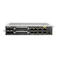
Figure 3.46 — MSS-1c rear view
3.10.1.1 — External user interface
• 2 traffic 10/100/1000 Base-T Ethernet interfaces for data and service traffic via RJ45
connector
Note: To use the User Ethernet Ports 3 and 4 an SFP plug-in (electrical or optical) must
be installed
Note: The meanings of the six LEDs are:
• LED M: Major Alarm (red)
• LED m: Minor Alarm (red) (not supported in the current release: permanently OFF)
• LED W: Warning (yellow) (not supported in the current release: permanently OFF)
• LED A: Abnormal condition (yellow)
• LED MPT1: MPT Status (green/red/yellow)
• LED MPT2: not supported
LED A is ON in the following conditions:
• Tx Power muted by operator
• ACM frozen by operator
• MPT loopback active
LED MPT1 can be:
• GREEN: MPT is emitting power as expected according the known configuration
• YELLOW: MPT is not emitting power due to a forced Squelch condition
• RED: MPT is ABNORMALLY emitting power
• SWITCHED OFF: MPT is not emitting power according with the known configuration
At start-up the MSS-1c:
• lights on all the alarm LEDs (Major, Minor, Warning and Abnormal)
• lights on the MPT LED as yellow, then this LED will be GREEN, RED or YELLOW, as
explained above.

 Loading...