Chapter 4: Powering On the Chassis
100
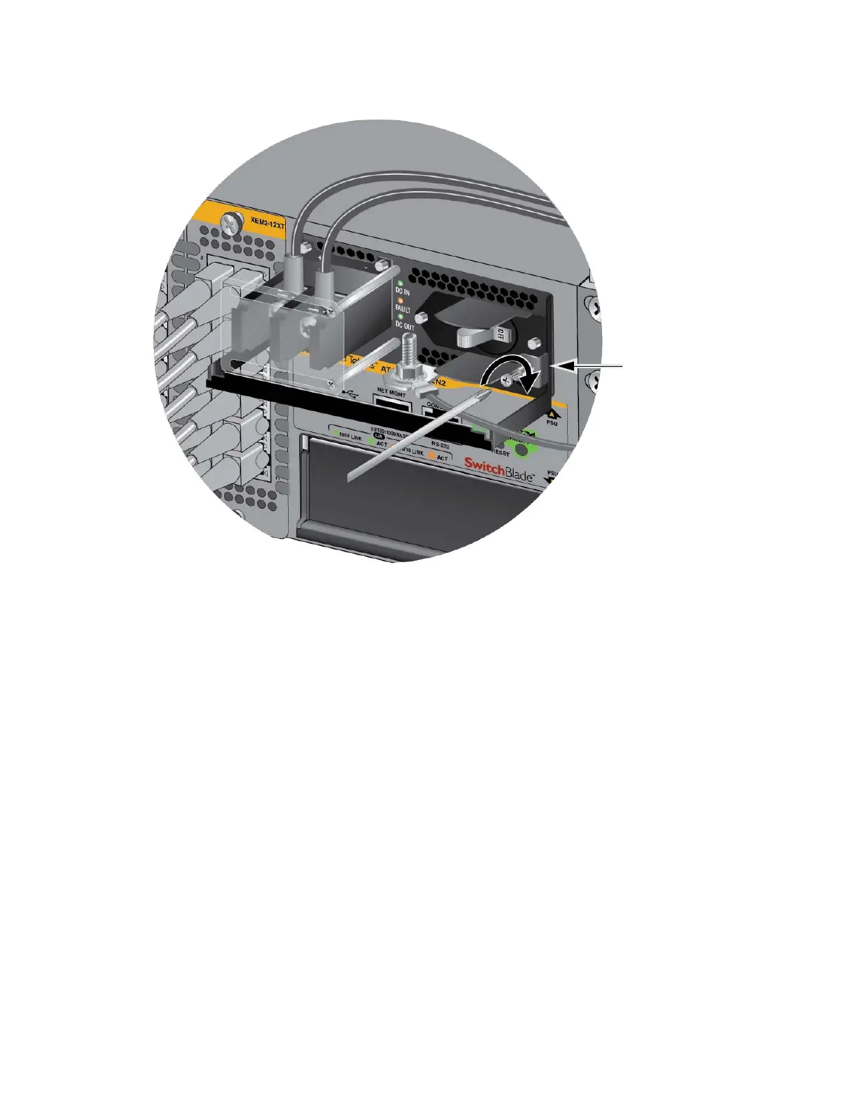
Figure 69. Tightening the Handle Locking Screw
10. Before attaching the power wires from the power supply to the circuit
breaker in the wiring closet, check that the circuit breaker is off.
11. Connect the power wires to the circuit breaker.
12. If you have two AT-SBxPWRSYS1-80 DC Power Supplies for the
switch, repeat this procedure to install the second power supply.
13. Turn the DC circuit breaker(s) on.
14. Turn the On/Off switch(es) on the AT-SBxPWRSYS1-80 DC Power
Supply(ies) to the On position. See Figure 54 on page 87.
15. Go to “Monitoring the Initialization Processes” on page 111.
Connecting the
DC Power Wires
with the Right
Angle Terminals
To use the right angle terminals to connect the DC power wires to the
positive and negative terminals on the AT-SBxPWRSYS1-80 DC Power
Supply, perform the following procedure:
1. Prepare adequate lengths of two stranded 8 AWG power wires by
stripping them as shown in Figure 62 on page 94.
 Loading...


