Chapter 2: Beginning the Installation
46
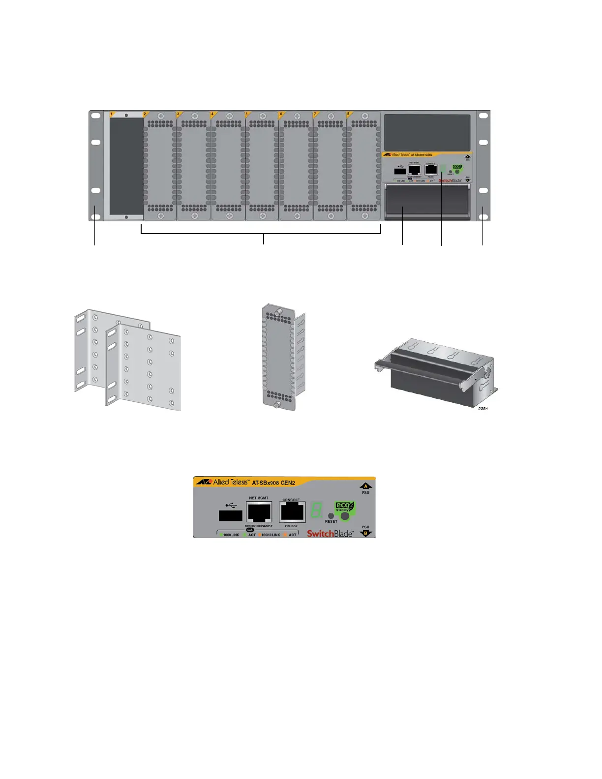
3. Visually inspect the front panel of the switch for the pre-installed
components identified in Figure 13.
Figure 13. Pre-installed Items on the Front and Side Panels
4. Visually inspect the rear panel for the pre-installed components
identified in Figure 14 on page 47.
2. Seven line card slot
covers
1. Two equipment rack
brackets
3. One blank panel in power
supply slot B
1 1
2
3
4
4. One management panel
(Not field replaceable.)
 Loading...


