AT-x908 Gen2 Switch Installation Guide
21
AT-SBx908 Gen2 Chassis
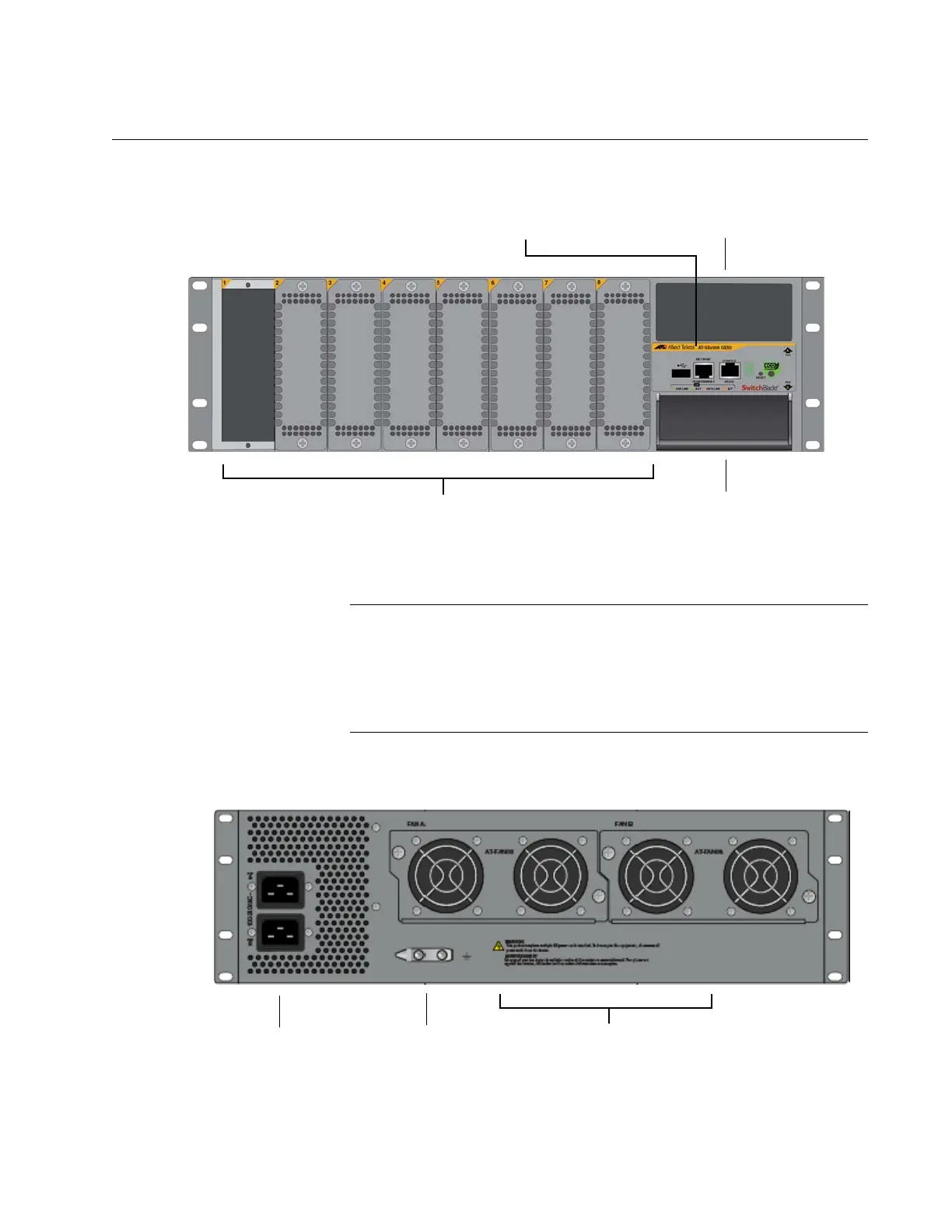
The front panel of the AT-SBx908 Gen2 Chassis is shown in Figure 1.
Figure 1. Front Panel of the AT-SBx908 Gen2 Chassis
The switch comes with slot covers on line card slots 2 to 8. Do not
remove the slot covers until after the unit is installed in the
equipment rack. You might bend the chassis and cause
misalignment of the slots and card guides if you lift the chassis into
the equipment rack without the line card slot covers.
The rear panel is shown in Figure 2.
Figure 2. Rear Panel of the AT-SBx908 Gen2 Chassis
Eight Slots for Ethernet Line Cards
Power Supply Slot (PSU A)
Power Supply Slot (PSU B)
with Blank Cover
Management Panel
Ground Wire Lug
AC Input
Power Connectors
AT-FAN08 Fan Units
 Loading...


