Chapter 3: Installing the Chassis
58
Installing the Chassis Grounding Wire
This procedure explains how to connect a grounding wire to the chassis.
The chassis requires a permanent connection for the line cards and power
supplies to a good earth ground. The procedure requires the following
items:
Grounding lug (pre-installed on the rear panel of the chassis)
#2 Phillips-head screwdriver (not provided)
Crimping tool (not provided)
10 AWG stranded grounding wire (not provided)
To connect the chassis to an earth ground, perform the following
procedure:
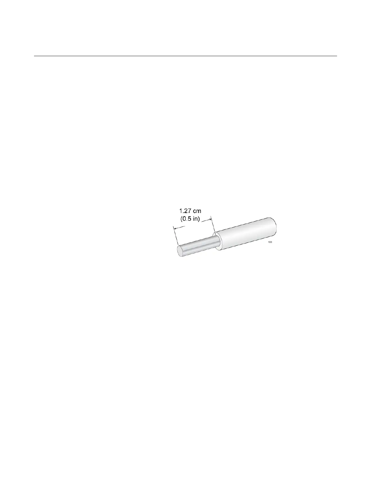
1. Prepare an adequate length of stranded grounding wire (10 AWG) for
the ground connection by stripping it as shown in Figure 23.
Figure 23. Stripping the Grounding Wire
2. Use a #2 Phillips-head screwdriver to remove the two screws that
secure the grounding lug to the rear panel of the chassis. Refer to
Figure 24 on page 59.
 Loading...


