AT-SBx908 Gen2 Switch Installation Guide
85
“Connecting Bare DC Power Wires” on page 107
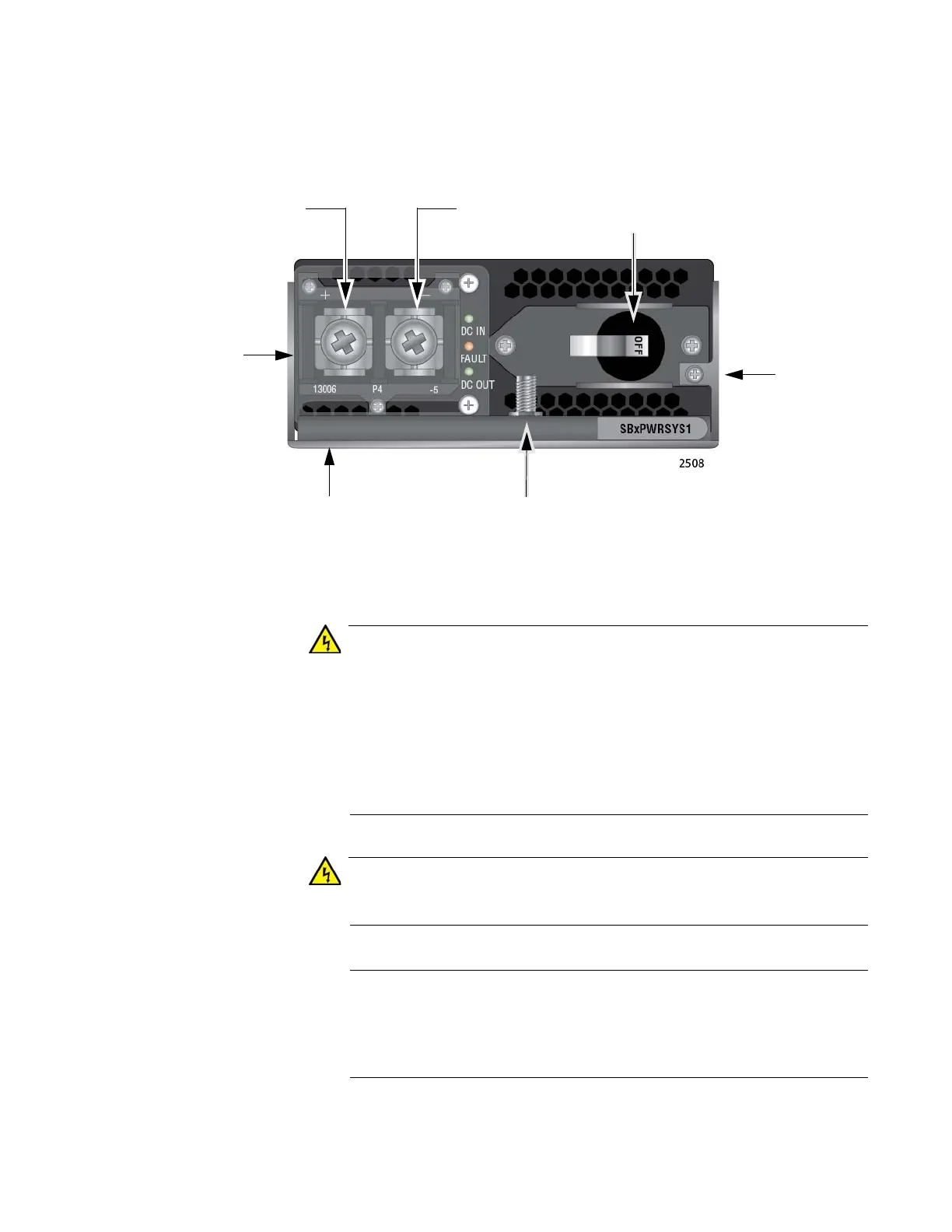
The components on the power supply are identified in Figure 50.
Figure 50. Components on the AT-SBxPWRSYS1-80 DC Power Supply
As a safety precaution, install a circuit breaker with a minimum value
of 50 Amps between the equipment and the DC power source.
Always connect the wires to the LAN equipment first before you
connect the wires to the circuit breaker. Do not work with HOT feeds
to avoid the danger of physical injury from electrical shock. Always
be sure that the circuit breaker is in the OFF position before
connecting the wires to the breaker. E9
For centralized DC power connection, install only in a restricted
access area. E23
A tray cable is required to connect the power source if the unit is
powered by centralized DC power. The tray cable must be a UL
listed Type TC tray cable and rated at 600 V and 90 degrees C, with
two conductors, 8 AWG. E24
Positive (+)
Terminal
Negative (-)
Terminal
On/Off
Switch
Locking
Handle
Locking
Handle
Screw
Plastic
Cover
Ground Post
with Nut and
Washer
 Loading...


