Home
Allied Telesis
Switch
AT-SBx908 Gen2
Allied Telesis AT-SBx908 Gen2 User Manual
4
of 1
of 1 rating
168 pages
Give review
Manual
Specs
To Next Page
To Next Page
To Previous Page
To Previous Page
Loading...
Chapter 6: Rep
lacing Modules
152
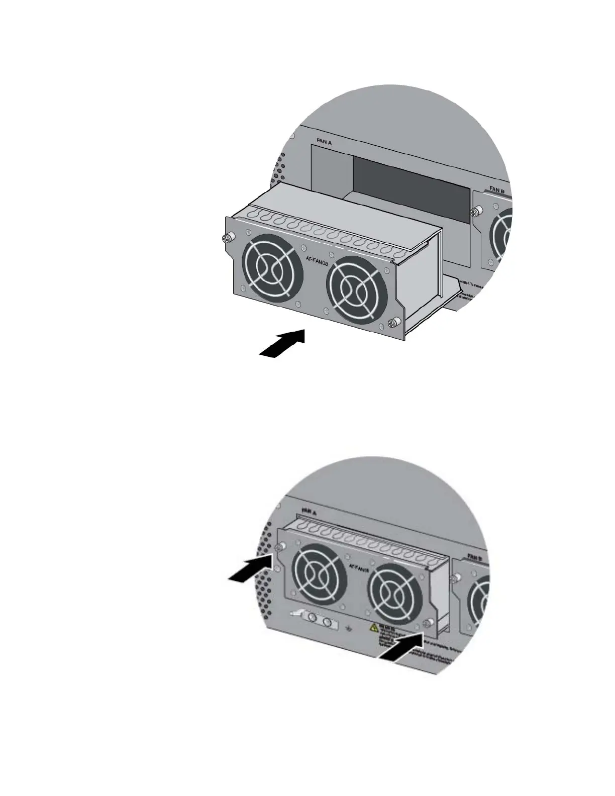
Figure 113. Aligning the AT-FAN08 Module in
the Chassis Slot
2.
When you feel the module make co
ntact with the connector inside the
chassis, gently press on both
sides to seat
the module on the
connector. Refer to Figure
114.
Figure 114. Seating the AT-FAN08 Module on the Connector in the
Chassis
151
153
Table of Contents
Default Chapter
1
Installation Guide
1
Electrical Safety and Emissions Standards
3
Translated Safety Statements
4
Table of Contents
5
Preface
13
Document Conventions
14
Contacting Allied Telesis
15
Chapter 1: Overview
17
Overview
18
Table 1: Features of the AT-Sbx908 Gen2 Chassis
18
AT-Sbx908 Gen2 Chassis
21
Figure 1: Front Panel of the AT-Sbx908 Gen2 Chassis
21
Figure 2: Rear Panel of the AT-Sbx908 Gen2 Chassis
21
Ethernet Line Cards
22
Figure 3: AT-Sbx908 Gen2 Ethernet Line Cards
22
AT-XEM2-12XT Line Card
23
Table 2: Twisted Pair Ports on the AT-XEM2-12XT Line Card
23
Table 3: Link and Activity Leds on the AT-XEM2-12XT Line Card
23
AT-XEM2-12XS Line Card
25
Table 4: Link and Activity Leds on the AT-XEM2-12XS Line Card
25
AT-XEM2-4QS Line Card
26
Table 5: Link and Activity Status Leds for the AT-XEM2-4QS Line Card
26
Management Panel
27
USB Port
27
Figure 4: Management Panel
27
NET MGMT Ethernet Management Port
28
Table 6: Twisted Pair Cable for the NET MGMT Port on the Management Panel
28
Console (RS-232) Port
29
Switch ID LED
29
Table 7: NET MGMT Port LED
29
Eco-Friendly Button
30
Reset Button
30
Figure 5: Switch ID LED
30
Power Supplies
32
Figure 6: AT-Sbxpwrsys2 and AT-Sbxpwrsys1-80 Power Supplies
32
AT-FAN08 Units
34
Figure 7: AT-FAN08 Module
34
Specifying Ports in the Command Line Interface
35
Figure 8: PORT Parameter in the Command Line Interface
35
Table 8: PORT Parameter Format
35
Chapter 2: Beginning the Installation
37
Reviewing Safety Precautions
38
Choosing a Site for the Chassis
43
Figure 9: NEMA 5-20P Plug and Receptacle
43
Unpacking the Chassis
44
Figure 10: AT-Sbx908 Gen2 Switch Shipping Box
44
Figure 11: Lifting the Switch from the Shipping Box
45
Figure 12: Removing the Switch from the Protective Shipping Bag
45
Figure 13: Pre-Installed Items on the Front and Side Panels
46
Figure 14: Pre-Installed Items on the Rear Panel
47
Figure 15: Accessory Kit
48
Unpacking AT-Sbxpwrsys2 AC Power Supplies
49
Figure 16: Items in the Shipping Box for the AT-Sbxpwrsys2 AC Power Supply
49
Unpacking AT-Sbxpwrsys1-80 DC Power Supplies
50
Figure 17: Items in the Shipping Box for the AT-Sbxpwrsys1-80 DC Power Supply
50
Chapter 3: Installing the Chassis
51
Tools and Material
52
Adjusting the Equipment Rack Brackets
53
Figure 18: Chassis Orientations in the Equipment Rack
53
Figure 19: Chassis Orientations in the Equipment Rack (Continued)
54
Figure 20: Chassis Orientations in the Equipment Rack (Continued)
55
Figure 21: Example of Adjusting the Equipment Rack Brackets
56
Installing the Chassis in an Equipment Rack
57
Figure 22: Securing the Chassis to the Equipment Rack
57
Installing the Chassis Grounding Wire
58
Figure 23: Stripping the Grounding Wire
58
Figure 24: Removing the Grounding Lug from the Chassis
59
Figure 25: Attaching the Grounding Wire to the Grounding Lug
59
Figure 26: Installing the Grounding Lug and Wire
60
Installing AT-Sbxpwrsys2 AC Power Supplies
61
Figure 27: Removing the Blank Power Supply Panel from Power Supply Slot B
62
Figure 28: Lifting the Locking Handle on the AT-Sbxpwrsys2 Power Supply
62
Figure 29: Sliding the AT-Sbxpwrsys2 AC Power Supply into the Chassis
63
Figure 30: Lowering the Locking Handle on the AT-Sbxpwrsys2 AC Power Supply
64
Installing AT-Sbxpwrsys1-80 DC Power Supplies
65
Figure 31: On/Off Switch on the AT-Sbxpwrsys1-80 DC Power Supply
66
Figure 32: Loosening the Handle Locking Screw on the AT-Sbxpwrsys1-80 DC Power Supply
66
Figure 33: Lifting the Locking Handle on the AT-Sbxpwrsys1-80 DC Power Supply
67
Figure 34: Inserting the AT-Sbxpwrsys1-80 DC Power Supply
67
Figure 35: Lowering the Locking Handle on the AT-Sbxpwrsys1-80 DC Power Supply
68
Installing Ethernet Line Cards
69
Figure 36: Removing a Blank Line Card Cover
69
Figure 37: Removing the Ethernet Line Card from the Anti-Static Bag
70
Figure 38: Sliding the Ethernet Line Card into the Slot
71
Figure 39: Seating an Ethernet Line Card in the Chassis
72
Figure 40: Tightening the Two Captive Screws on the Ethernet Line Card
72
Installing Blank Line Card Slot Covers
73
Figure 41: Installing a Blank Slot Cover
73
Figure 42: Tightening the Captive Screws on a Blank Slot Cover
74
Installing the Blank Power Supply Slot Cover
75
Figure 43: Lifting the Locking Handle on the Blank Power Supply Slot Cover
75
Figure 44: Aligning the Blank Power Supply Cover in the Slot
76
Figure 45: Lowering the Locking Handle on the Blank Power Supply Slot Cover
76
Installing the Power Cord Retaining Clips
77
Figure 46: Installing the Power Cord Retaining Clips
77
Chapter 4: Powering on the Chassis
79
Verifying the Installation
80
Powering on AT-Sbxpwrsys2 Power Supplies
81
Figure 47: Connecting the AC Power Cord
82
Figure 48: Securing the Power Cord with the Retaining Clip
82
Figure 49: Connecting the Power Cord to an AC Power Source
83
Powering on AT-Sbxpwrsys1-80 DC Power Supplies
84
Figure 50: Components on the AT-Sbxpwrsys1-80 DC Power Supply
85
Choosing a Method for Attaching the Grounding Wire
86
Connecting the Grounding Wire with the Grounding Terminal
86
Figure 51: Grounding Wire Terminal
86
Figure 52: Stripping the Stranded Grounding Wire
86
Figure 53: Attaching the Stranded Grounding Wire to the Grounding Terminal
86
Figure 54: On/Off Switch on the AT-Sbxpwrsys1-80 DC Power Supply
87
Figure 55: Removing the Nut and Washer from the Grounding Post
88
Figure 56: Attaching the Grounding Lug and Wire to the Grounding Post
89
Figure 57: Securing the Grounding Wire
90
Connecting the Grounding Wire with Bare Wire
91
Figure 58: Stripping the Solid or Stranded Grounding Wire
91
Figure 59: Attaching the Bare Grounding Wire to the Grounding Post
91
Figure 60: Securing the Bare Grounding Wire to the Grounding Post
92
Choosing a Method for Attaching the Power Wires
93
Connecting the DC Power Wires with the Straight Terminals
93
Figure 61: Power Wire Terminals
93
Figure 62: Stripping the Power Wires
94
Figure 63: Attaching the Power Wires to the Straight Terminal Lugs
94
Figure 64: Opening the Plastic Cover
95
Figure 65: Removing the Terminal Screws
96
Figure 66: Connecting the Positive (+) Power Wire with a Straight Terminal
97
Figure 67: Connecting the Negative (-) Power Wire with a Straight Terminal
98
Figure 68: Closing the Plastic Cover over the Terminal Connectors
99
Connecting the DC Power Wires with the Right Angle Terminals
100
Figure 69: Tightening the Handle Locking Screw
100
Figure 70: Stripping the Power Wires
101
Figure 71: Attaching the Power Wires to the Right Angle Terminal Lugs
101
Figure 72: Removing the Plastic Cover
102
Figure 73: Removing the Terminal Screws
103
Figure 74: Connecting the Positive (+) Power Wire with a Right Angle Terminal
104
Figure 75: Connecting the Negative (-) Power Wire with a Right Angle Terminal
105
Figure 76: Tightening the Handle Locking Screw
106
Connecting Bare DC Power Wires
107
Figure 77: Stripping Solid or Stranded DC Power Wires
107
Figure 78: Connecting the Positive Wire with Bare Wire
108
Figure 79: Connecting the Negative Lead Wire with Bare Wire
109
Monitoring the Initialization Processes
111
Figure 80: Switch Initialization Messages
111
Figure 81: Switch Initialization Messages (Continued)
112
Figure 82: Switch Initialization Messages (Continued)
113
Verifying the Hardware Operations of the Chassis
114
Starting a Local Management Session
114
Figure 83: Connecting the Management Cable to the Console RS-232 Port
114
Verifying the Chassis with the Alliedware Plus Commands
115
Figure 84: SHOW CARD Command
116
Chapter 5: Cabling the Networking Ports
117
Cabling the 1Gbps or 10Gbps Ports on the AT-XEM2-12XT Line Card
118
Guidelines to Handling SFP, SFP+, and QSFP+ Transceivers
119
Installing 1Gbase SFP or 10Gbase SFP+ Transceivers in AT-XEM2-12XS Line Cards
120
Installing 1Gbase SFP or 10Gbase SFP+ Transceivers in AT-XEM2- 12XS Line Cards
120
Figure 85: Installing an SFP Transceiver
120
Figure 86: Removing the Dust Cover from an SFP or SFP+ Transceiver
121
Figure 87: Positioning the SFP or SFP+ Handle in the Upright Position
121
Figure 88: Connecting a Fiber Optic Cable to an SFP or SFP+ Transceiver
122
Installing AT-SP10TW Direct Connect Twinax Cables in the AT-XEM2-12XS Switch
123
Installing AT-SP10TW Direct Connect Twinax Cables in the AT-XEM2- 12XS Switch
123
Figure 89: Installing AT-SP10TW Cables in the AT-XEM2-12XS Line Card
123
Installing AT-QSFPSR4 or AT-QSFPLR4 Transceivers in QSFP+ Slots
125
Installing AT-QSFPCU Cables in QSFP+ Slots
126
Figure 90: Removing the Dust Cover from a Slot on the AT-XEM2-4QS Line Card
126
Figure 91: Sliding the AT-QSFPCU Cable into the Slot
127
Chapter 6: Replacing Modules
129
Replacing AT-Sbxpwrsys2 AC Power Supplies
130
Figure 92: Disconnecting the AC Power Cord from the Power Source
131
Figure 93: Disconnecting the AC Power Cord from the Chassis
131
Figure 94: Lifting the Locking Handle on the AT-Sbxpwrsys2 AC Power Supply
132
Figure 95: Removing the AT-Sbxpwrsys2 AC Power Supply
133
Replacing AT-Sbxpwrsys1-80 DC Power Supplies
134
Figure 96: Loosening the Screw on the Locking Handle
134
Figure 97: Opening the Plastic Window over the Terminal Block
135
Figure 98: Removing the Negative Lead Wire
136
Figure 99: Removing the Positive Lead Wire from the Terminal Block
137
Figure 100: Reinstalling the Screws on the Positive and Negative Terminals
138
Figure 101: Closing the Plastic Cover
139
Figure 102: Removing the Grounding Wire
140
Figure 103: Reinstalling the Nut and Washer on the Grounding Post
141
Figure 104: Lifting the Locking Handle and Removing the Power Supply
142
Figure 105: Installing the Blank Power Supply Slot Cover
143
Figure 106: Lowering the Locking Handle on the Power Supply Slot Cover
144
Removing Ethernet Line Cards
145
Figure 107: Loosening the Screws on the Ethernet Line Card
146
Figure 108: Disconnecting an Ethernet Line Card from the Chassis
147
Figure 109: Sliding an Ethernet Line Card from the Chassis
148
Figure 110: Placing the Ethernet Line Card in Its Anti-Static Bag
149
Replacing AT-FAN08 Modules
150
Removing AT-FAN08 Modules
150
Figure 111: Loosening the Screws on the AT-FAN08 Module
150
Installing AT-FAN08 Modules
151
Figure 112: Disconnecting the AT-FAN08 Module from the Chassis
151
Figure 113: Aligning the AT-FAN08 Module in the Chassis Slot
152
Figure 114: Seating the AT-FAN08 Module on the Connector in the Chassis
152
Figure 115: Tightening the Two Captive Screws on the AT-FAN08 Module
153
Chapter 7: Troubleshooting
155
Appendix A: Technical Specifications
159
Physical Specifications
160
Table 9: Product Dimensions
160
Table 10: Product Weights
160
Table 11: Ventilation Requirements
161
Environmental Specifications
162
Table 12: Environmental Specifications
162
Power Specifications
163
Table 13: AC Voltage and Frequency Requirements
163
Table 14: DC Voltage Requirements
163
Table 15: Maximum Power Consumption (Watts)
163
Table 16: Typical Power Savings in Eco-Friendly Mode (Watts)
163
Table 17: Maximum Power Supply Efficiency (Based on 100V Input Voltage)
164
Table 18: Heat Dissipation (British Thermal Units/Hour)
164
Certifications
165
Table 19: Product Certifications
165
Port Pinouts
166
Figure 116: Pin Layout (Front View) of the 1Gbps or 10Gbps Ports on the AT-XEM2-12XT Line Card
166
Table 20: Pin Signals for 1Gbps or 10Gbps
166
Table 21: RJ-45 Pin Signals for the Console Port on the Management Panel
167
Table 22: RJ-45 Pin Signals for 10 or 100Mbps for the NET MGMT Port on the Management Panel
167
4
Based on 1 rating
Ask a question
Give review
Questions and Answers:
Need help?
Do you have a question about the Allied Telesis AT-SBx908 Gen2 and is the answer not in the manual?
Ask a question
Allied Telesis AT-SBx908 Gen2 Specifications
General
Brand
Allied Telesis
Model
AT-SBx908 Gen2
Category
Switch
Language
English
Related product manuals
Rapier i AT-RP16Fi/SC
123 pages
Allied Telesis AT-9028
1278 pages
Allied Telesis AT-GS950
46 pages
Allied Telesis AT-FS716
44 pages
Allied Telesis AT-8026T
116 pages
Allied Telesis AT-FS708
48 pages
Allied Telesis AT-8350GB
104 pages
Allied Telesis AT-GS924MX
118 pages
Allied Telesis AT-9000/28
1276 pages
Allied Telesis AT-GS910/8
70 pages
Allied Telesis AT-RS710TX
48 pages
Allied Telesis AT-8624PoE
36 pages