Appendix A: Technical Specifications
166
Port Pinouts
The port pinouts are given in the following subsections.
AT-XEM2-12XT Line Card
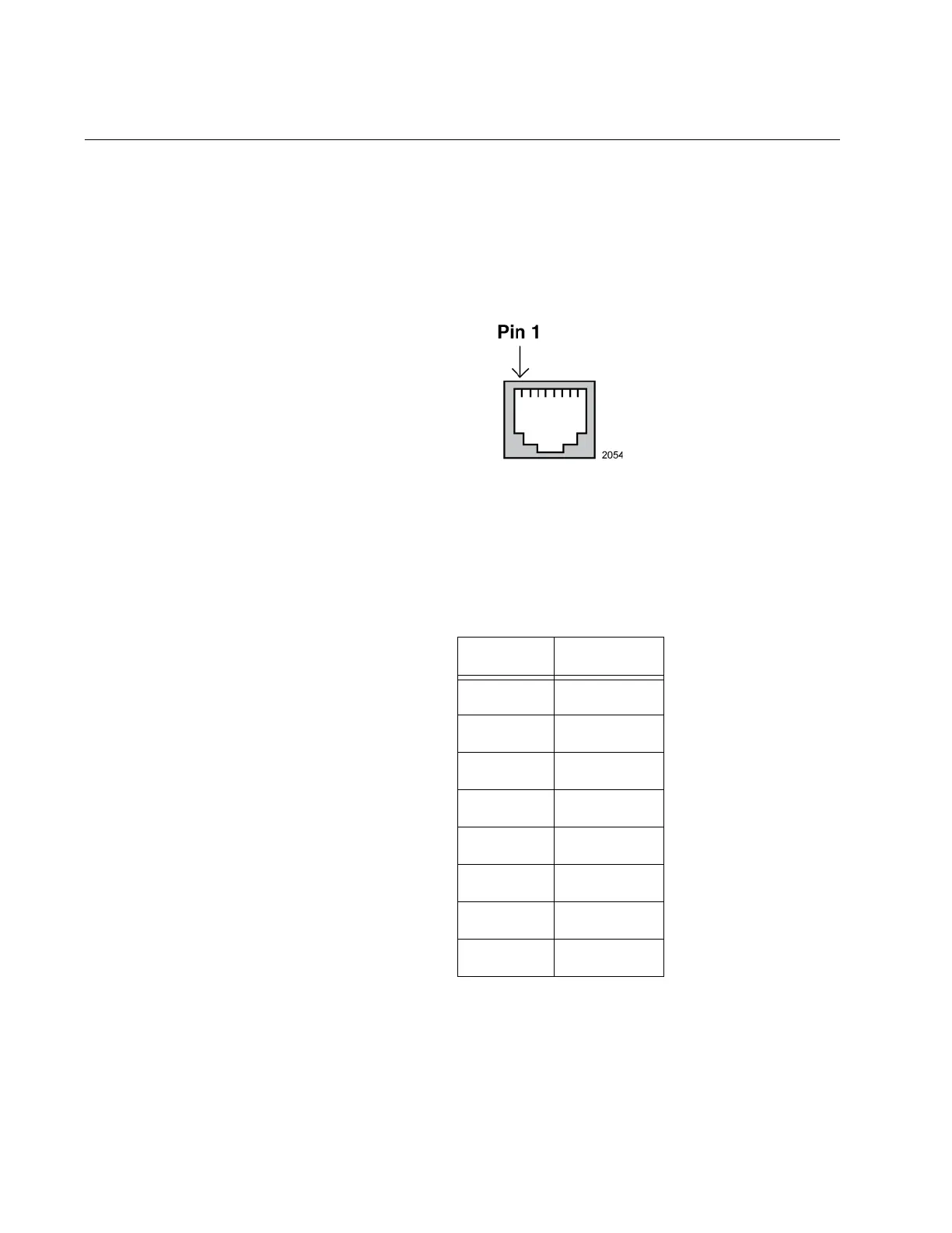
Figure 116 illustrates the pin layout of the RJ-45 connectors of the 1Gbps
or 10Gbps ports on the AT-XEM2-12XT Line Card.
Figure 116. Pin Layout (Front View) of the 1Gbps or 10Gbps Ports on the
AT-XEM2-12XT Line Card
Table 20 lists the pin signals when a port operating at 1GBase or
10GBase.
Console Port on the Management Panel
Table 21 lists the pin signals of the RJ-45 style serial Console port on the
management panel.
Table 20. Pin Signals for 1Gbps or 10Gbps
Pinout Pair
1Pair 1 +
2Pair 1 -
3Pair 2 +
4Pair 3 +
5Pair 3 -
6Pair 2 -
7Pair 4 +
8Pair 4 -
 Loading...


