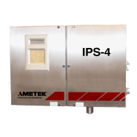
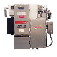
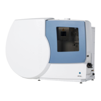
What to do for Span Cal Failure warning on Ametek IPS-4 Measuring Instruments?
- SScott WernerSep 12, 2025
If a span calibration failure has occurred on your Ametek Measuring Instruments, you should perform a successful span calibration.

 Loading...
What to do for Span Cal Failure warning on Ametek IPS-4 Measuring Instruments?
If a span calibration failure has occurred on your Ametek Measuring Instruments, you should perform a successful span calibration.
What should I do if I see a Zero Cal Failure warning on my Ametek Measuring Instruments?
If a zero calibration failure has occurred on your Ametek Measuring Instruments, perform a successful zero calibration.
| Brand | Ametek |
|---|---|
| Model | IPS-4 |
| Category | Measuring Instruments |
| Language | English |
Details analytes, linearity, accuracy, repeatability, stability, and drift.
Covers inputs, outputs, sample system limits, and electrical requirements.
Specifies operating conditions, approvals, and certifications.
Highlights high voltage hazards, grounding requirements, and precautions.
Provides essential warnings for safe operation, maintenance, and handling.
Important precautions for handling electronic components and sensitive parts.
Recommendations for wiring and installation to prevent electromagnetic disturbances.
Lists directives and standards met, including EMC, RoHS, and LVD.
Provides the EU-Type Examination Certificate number, product details, and marking.
Details warranty coverage, duration, exclusions, and liabilities.
Describes the dual bench setup and basic measurement principles.
Illustrates information flow and calculation steps for analyzer output.
Details the DUVV bench design, wavelength ranges, accuracy, and resolution.
Details the NDIR bench design, wavelength ranges, and photometric specs.
Covers the sample system enclosure, components, and configuration options.
Explains the detector, MCU, and other boards and their primary functions.
Details protection methods like pressurization (Type 'p') and flameproof enclosures (Type 'd').
Lists key performance metrics: analytes, linearity, accuracy, repeatability, stability, drift.
Covers inputs, outputs, sample system limits, electrical, and environmental specs.
Lists ATEX, IECEx, PED, EMC, LVD, and RoHS compliance.
Emphasizes safety review, storage, and initial inspection before installation.
Covers installing optical benches, sample systems, and electrical connections.
Details the start-up sequence for purged analyzers using the MiniPurge system.
Steps for powering up, performing checks, and verifying operation.
Introduces the UI panel, keys, and navigation functions.
Explains working in main menus, HOME screen, system status, and alarms.
Accesses sub-menus like Calibration, Relays, Outputs, Diagnostics.
Configures auto-calibration, flush times, and calibration actions.
Setup and configuration of up to eight relays for operational status.
Configures analog output assignments, full-scale, zero values, and type.
View and modify span, pressure, and temperature limits.
Test current outputs, relays, valves, and lamps for troubleshooting.
Set up password protection for configuration changes and parameter access.
Save or restore analyzer configuration settings to PC or factory defaults.
Configure network settings and Modbus parameters for analyzer communication.
View model, serial, software version, time, date, and customize display.
Emphasizes safety review and precautions before performing maintenance.
Outlines recommended routine maintenance tasks for optimal operation and component life.
Methods for identifying plugs by monitoring response time and cell pressure.
Discusses replacing parts like heaters, RTDs, or boards as per maintenance schedule.
Procedures for cleaning the cell, replacing o-rings, windows, and checking for damage.
Step-by-step guide for safely replacing the Xenon flash lamp assembly.
Step-by-step guide for safely replacing the Infrared source assembly.
Lists analyzer alarm messages, their triggers, and suggested corrective actions.
Steps for safely resetting the analyzer, typically after configuration changes.
Contact information and procedures for obtaining technical and service assistance.
Process for returning equipment for repair and warranty validation.
Lists essential spare parts for on-site maintenance and optimal analyzer operation.
Overview of accessing and navigating the analyzer's web interface.
Displays operational status, analyte concentrations, and calibration requirements.
How to access and view current active alarms and warnings through the web interface.
Displays trends of selected parameters, data is not saved.
Allows temporary storage and comparison of spectral data for troubleshooting.
Accesses sub-menus for calibration, outputs, relays, network, and diagnostics.
Configure network settings and Modbus parameters for analyzer communication.
Test current outputs, relays, valves, and lamps for troubleshooting via web interface.
Details Modbus protocol, RS-485 connection, jumpers, and parameters.
Provides light path schematics for UV and NDIR optical benches.
Illustrates overall component layouts and detailed wiring diagrams for electronic boards.
Lists additional documents like manual supplements, configuration sheets, and as-built drawings.


