104
Adjacent Channel Leakage Power Ratio (6.6.2.3) 3.1.30.
This chapter describes UL measurement examples where (Modulation, RB) is (QPSK, PartialRB), (QPSK, FullRB),
(16QAM, PartialRB) or (16QAM, FullRB).
[Pass/Fail evaluation limits value setting]
1. Execute ACLR_AVG 20 to set the average count of Adjacent Channel Power to 20 times.
2. Execute TP_ACLR_E -36.2 to set E-UTRA Pass/Fail limit value to –36.2 dB.
3. Execute TP_ACLR_U1 -32.2 UTRA
ACLR1
to set Pass/Fail limit value to –32.2 dB.
4. Execute TP_ACLR_U2 -35.2 UTRA
ACLR1
to set Pass/Fail limit value to –35.2 dB.
[(QPSK, PartialRB) measurements]
5. Execute TESTPRM TX_MAXPWR_Q_P to set Test Parameter to TX1 - Max. Power (QPSK/PartialRB).
6. Execute ULRB_POS MIN to set UL RB Position to Min (#0).
7. Execute SWP to measure the Adjacent Channel Power.
8. Execute MODPWRPASS? to check that the ACLR Pass/Fail judgment is Pass.
9. Execute ULRB_POS MAX to set UL RB Position to Max (#max).
10. Execute steps 7 to 8.
[(QPSK, FullRB) measurements]
11. Execute TESTPRM TX_MAXPWR_Q_F to set Test Parameter to TX1 - Max. Power (QPSK/FullRB).
12. Execute steps 7 to 8.
[(16QAM, PartialRB) measurements]
13. Execute TESTPRM TX_MAXPWR_16_P to set Test Parameter toTX1 - Max. Power (16QAM/PartialRB)).
14. Execute steps 6 to 10.
[(16QAM, FullRB) measurements]
15. TESTPRM TX_MAXPWR_16_F to set Test Parameter to TX1 - Max. Power (16QAM/FullRB).
16. Execute steps 7 to 8.
NOTE 1: The PartialRB allocation UL RB Position is divided as follows:
When Test Frequency is Low range, Max (#max)
When Test Frequency is Mid range, Min (#0) and Max (#max)
When Test Frequency is High range, Min (#0)
NOTE 2: At HPUE measurement, set a value that does not affect the decision limit for
UTRA
ACLR1
and UTRA
ACLR2
because they are not defined by 3GPP.
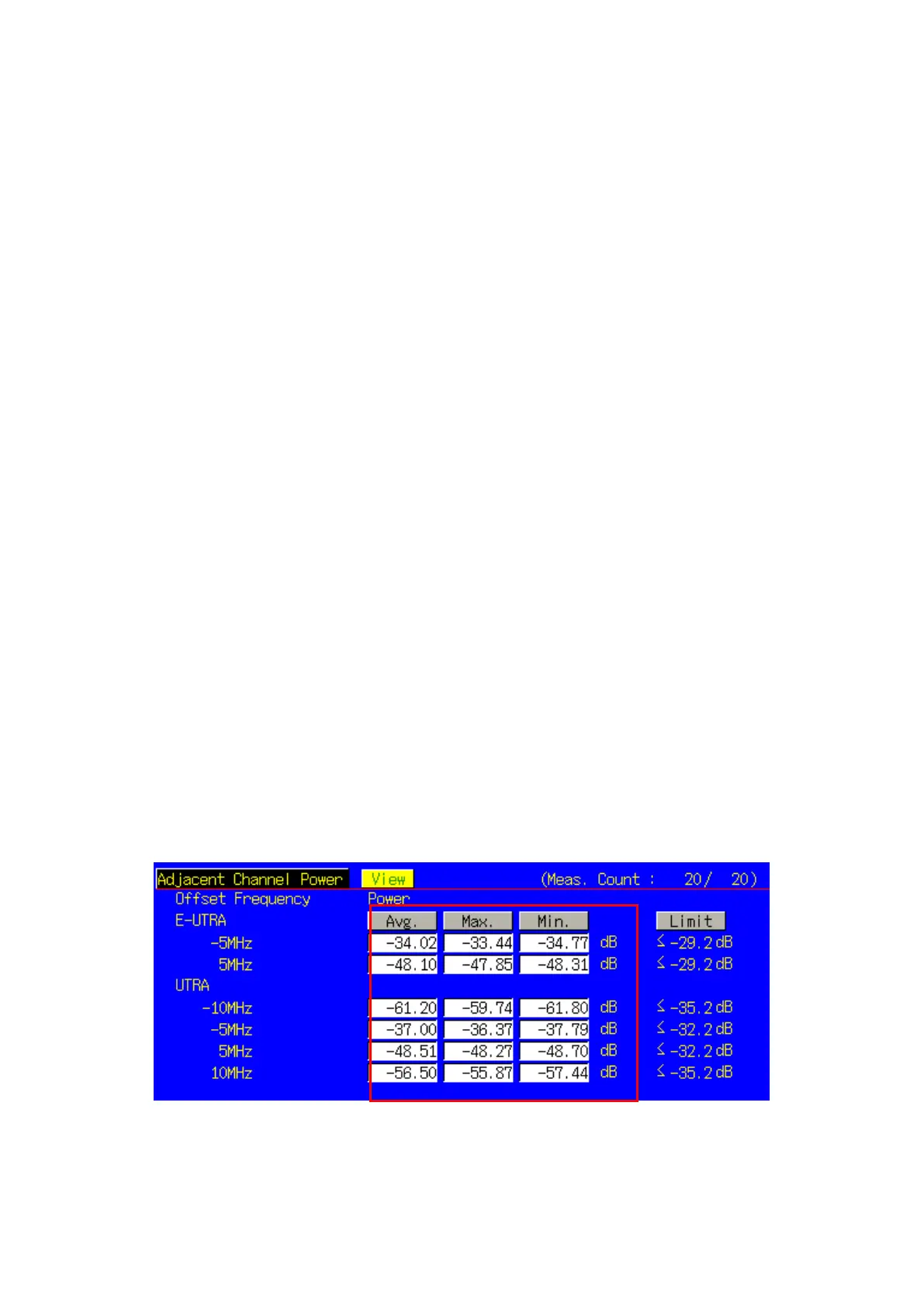
Figure 3.1.30-1 Example of Measurement Result when Test Parameter is TX1 - Max. Power (QPSK/PartialRB)
(MT8820C)