82
Configured UE transmitted Output Power for HPUE (6.2.5_1) 3.1.7.
The measurement can be performed using the same procedure as in Chapter 3.1.5.
For Test Point 4, add the following steps to the procedure.
13. Execute MAXULPWR 20 to set p-Max value to 20.
14. Execute steps 6 to 8.
Minimum Output Power (6.3.2) 3.1.8.
This chapter describes a UL measurement example where (Modulation, RB) is (QPSK, FullRB).
[Pass/Fail evaluation limits value setting]
1. Execute PWR_AVG 20 to set the average count of Power measurement to 20 times.
2. Execute TP_MINPWR_UL -39.0 to set TX1 - Min. Power Pass/Fail judgment.
[Measurements]
3. Execute TESTPRM TX_MINPWR to set Test Parameter to TX1 - Min. Power.
4. Execute SWP to measure the power.
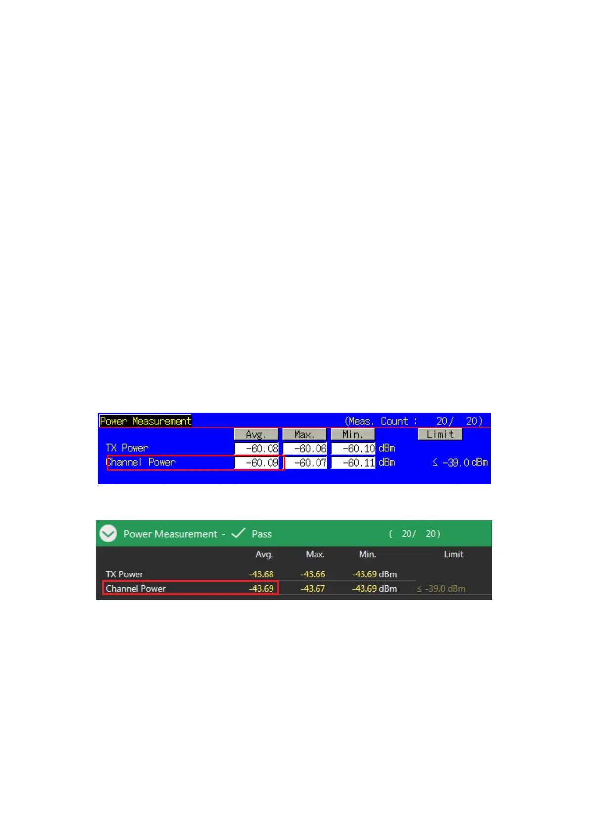
5. Execute CHPWR? AVG to read the Channel Power measurement result.
6. Execute CHPWRPASS? to check that the Channel Power measurement Pass/Fail judgment is Pass.
NOTE 1: The Pass/Fail evaluation value is initialized as described in TS36.521-1 Table 6.3.2.5-1 and used
when the Carrier Frequency is 3 GHz or less. When the Carrier Frequency exceeds 3 GHz, set:
TP_MINPWR_UL -38.7
as described in TS36.521-1 Table 6.3.2.5-1.
For the Pass/Fail evaluation values, refer to Chapter 3.7.4 Test Parameter Limit in the operation manual.
Figure 3.1.8-1 Example of Measurement Result when Test Parameter is TX1 - Min. Power (MT8820C)
Figure 3.1.8-2 Example of Measurement Result when Test Parameter is TX1 - Min. Power (MT8821C)