81
Configured UE transmitted Output Power (6.2.5) 3.1.6.
This chapter describes a UL measurement example where (Modulation, RB) is (QPSK, PartialRB).
[Pass/Fail evaluation limits value setting]
1. Execute PWR_AVG 20 to set the average count of Power measurement to 20 times.
2. Execute TP_CONFPWR1_TOL 7.7 to set TX2 - Configured UE transmitted Output Power (Test Point 1)
Pass/Fail Judgment.
3. Execute TP_CONFPWR2_TOL 6.7 to set TX2 - Configured UE transmitted Output Power (Test Point 2)
Pass/Fail Judgment.
4. Execute TP_CONFPWR3_TOL 5.7 to set TX2 - Configured UE transmitted Output Power (Test Point 3)
Pass/Fail Judgment.
[Measurements]
5. Execute TESTPRM TX_CONF_PWR1 to set Test Parameter to TX2 - Configured Power (Test Point 1).
6. Execute SWP to measure power.
7. Execute POWER? AVG to read the TX Power measurement result.
8. Execute POWERPASS? to check that the TX Power measurement Pass/Fail judgment is Pass.
9. Execute TESTPRM TX_CONF_PWR2 to set Test Parameter to TX2 - Configured Power (Test Point 2).
10. Execute steps 6 to 8.
11. Execute TESTPRM TX_CONF_PWR3 to set Test Parameter to TX2 - Configured Power (Test Point 3).
12. Execute steps 6 to 8.
NOTE 1: The UL RB Position of PartialRB allocation is Min (#0).
NOTE 2: The Pass/Fail evaluation value is initialized as described in TS36.521-1 Table 6.2.5.5-1 and used
when the Carrier Frequency is 3 GHz or less. When the Carrier Frequency exceeds 3 GHz, set
TP_CONFPWR1_TOL 8.0
TP_CONFPWR2_TOL 7.0
TP_CONFPWR3_TOL 6.0
as described in TS36.521-1 Table 6.2.5.5-1.
For the Pass/Fail evaluation values, refer to Chapter 3.7.4 Test Parameter Limit in the operation manual.
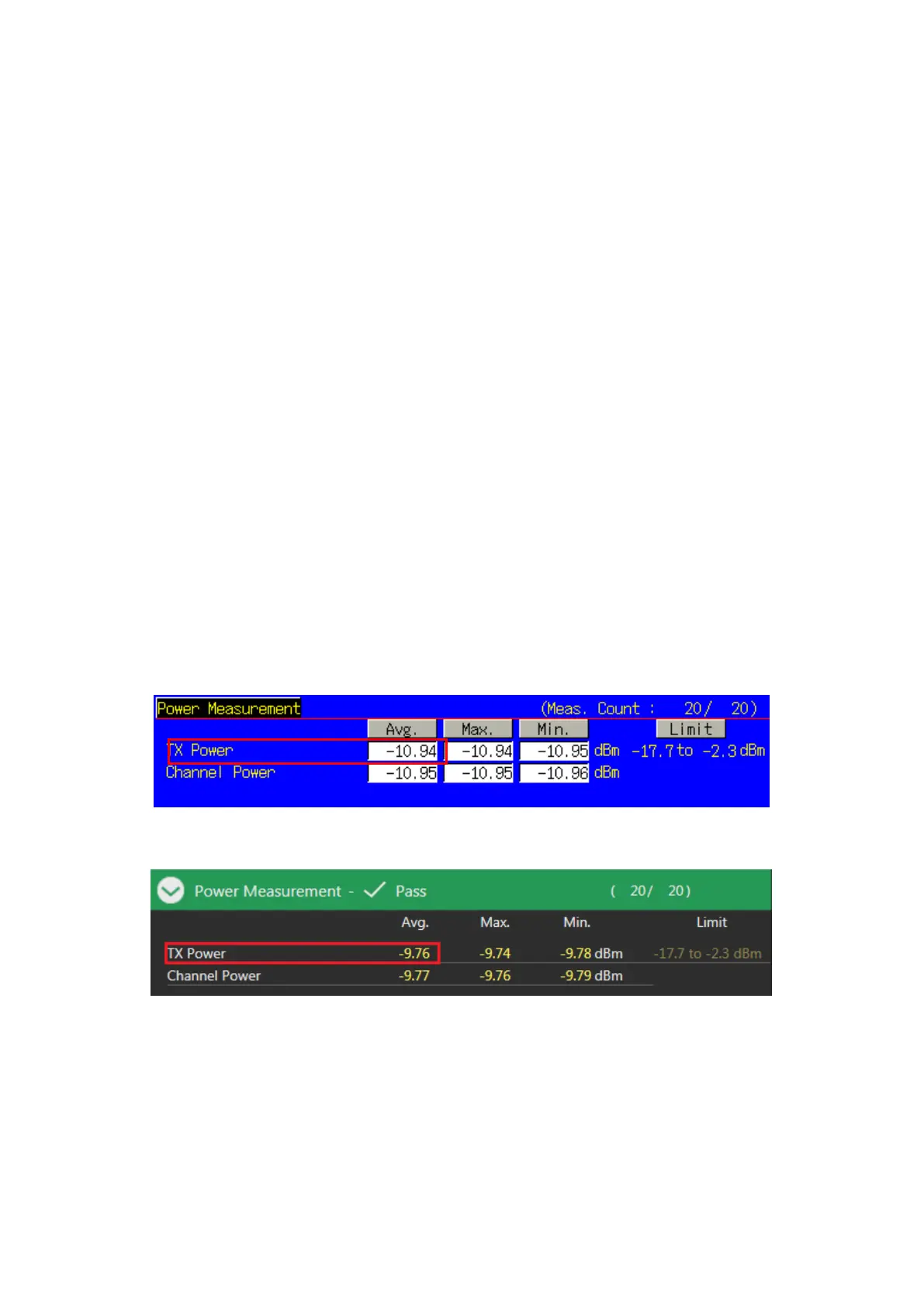
Figure 3.1.6-1 Example of Measurement Result when Test Parameter is TX2 - Configured Power (Test Point 1)
(MT8820C)
Figure 3.1.6-2 Example of Measurement Result when Test Parameter is TX2 - Configured Power (Test Point 1)
(MT8821C)