113
TX Measurements for CA 3.3.
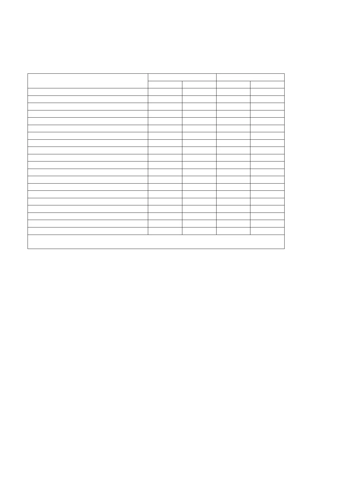
The following table describes inter–band UL CA and intra–band contiguous UL CA measurements supported by
MT8820C and MT8821C.
Table 3.3-1: UL CA measurements supported by MT8820C and MT8821C
TX Measurements for Inter-band CA 3.3.1.
Inter–band UL CA measurement is not specified in 3GPP TS 36.521–1, therefore Rel-8 measurement procedures are
applied to PCC and SCC in this Application NOTE.
The following test procedures are different between the MT8820C and MT8821C.
This chapter explains each test procedure for the MT8820C and MT8821C.
3.3.1.1. UE Maximum Output Power
3.3.1.1.1. MT8820C
[Acceptable Value Setting]
1. [PCC/SCC] Execute PWR_AVG 20 to set the average count for Power Measurement to 20
2. [PCC/SCC] Execute TP_MAXPWR_LL 20.3 to set TX1 – Max. Power (QPSK/1RB/PartialRB) Pass/Fail lower
limit to 20.3 dBm.
3. [PCC/SCC] Execute TP_MAXPWR_UL 25.7 to set TX1 – Max. Power (QPSK/1RB/PartialRB) Pass/Fail upper
limit to 25.7 dBm.
[(QPSK, 1RB) measurements]
4. [PCC/SCC] Execute TESTPRM TX_MAXPWR_Q_1 to set Test Parameter to TX1 – Max. Power(QPSK/1RB).
5. [PCC/SCC] Execute ULRMC_RB 1 to set UL RMC – Number of RB to 1.
6. [PCC/SCC] Execute ULRB_POS MIN to set UL RB Position to Min(#0).
7. [PCC/SCC] Execute SWP to measure the Power.
8. [PCC/SCC] Execute POWER? AVG to read the TX power measurement result.
9. [PCC/SCC] Execute POWERPASS? to check that the TX power measurement Pass/Fail judgment is Pass.
[(QPSK, PartialRB) measurements]
Maximum Power Reduction (MPR)
Additional Maximum Power Reduction (A–MPR)
Configured UE transmitted Output Power
Power Control Absolute power tolerance
Power Control Relative power tolerance
Aggregate power control tolerance
Error Vector Magnitude (EVM)
In-band emissions for non allocated RB
Additional Spectrum Emission Mask
Adjacent Channel Leakage power Ratio
Reference sensitivity level
NOTE 1: High–Speed Measurement Hardware (MT8820C–021/022) is not supported.
NOTE 2: MX882012C/42C Ver23.30 does not support CR (R4–153777).