170
BAND 13 SUPPLEMENTARY RF CONFORMANCE MEASUREMENT 4.
The following test procedure can be used with both the MT8820C and MT8821C.
PUCCH OVER-PROVISIONING FUNCTIONAL TEST (2.7) 4.1.
Check whether the allocated PUCCH performs the correct ACK/NACK report. Test at 10 MHz.
1. Execute BANDWIDTH 10MHZ to set Common Parameter - Channel Bandwidth to 10 MHz.
2. Connect to Test Mode.(2.1.4)
3. Execute TESTPRM RX_SENS to set Test Parameter to RX - Ref. Sens./Freq. Error.
4. Execute TPUT_SAMPLE 10000 to Rx Measurement Parameter - Throughput - Number of Sample to
10000.
5. Execute DLRMC_RB 50 to set Common Parameter - DLRMC - Number of RB to 50.
6. Execute CHCONFIG PUCCH to set Common Parameter - RMC Configuration to PUCCH.
7. Execute OLVL -91.0 to set Common Parameter - Output Level to –91.0 dBm.
8. Execute SIB2_NS NS_07 to set Call Processing Parameter - additional SpectrumEmission to NS_07.
9. Execute NRBCQI 26 to set Call Processing Parameter - nRB-CQI to 26.
10. Execute SWP to measure the Throughput.
11. Execute TPUT? PER to read Throughput measurement result (%).
12. Execute TPUTPASS? to check that the Throughput measurement Pass/Fail judgment is Pass.
13. Execute NRBCQI 28 to set Call Processing Parameter - nRB-CQI to 28.
14. Execute steps 10 to 12.
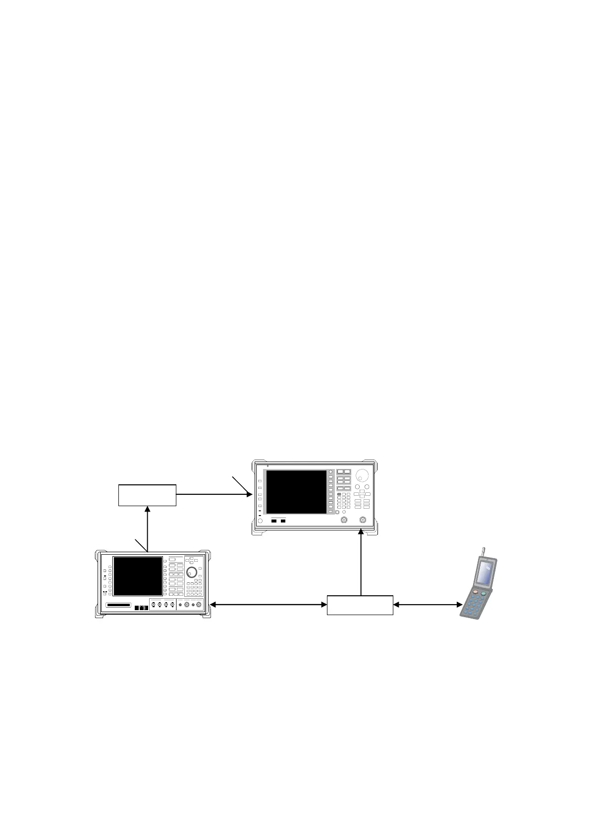
SPURIOUS EMISSIONS WITH TX GATING (2.9) 4.2.
Perform spurious emission tests using an external spectrum analyzer. Inputting the MT8821C frame signal to an
external spectrum analyzer using the MN8110 hardware option supports spurious emission measurements
synchronized with Tx Gating.
NOTE 1: Use Call Proc I/O for MT8821C and MN8110 connection.
NOTE 2: Use Frame Trigger Output connector for MN8110 output.
NOTE 3: Set Trigger source to External and Gate Length to 1 ms.
Figure 4.2-1 Setup for Spurious Emissions with Tx Gating Test