156
Connection Diagram 3.7.3.
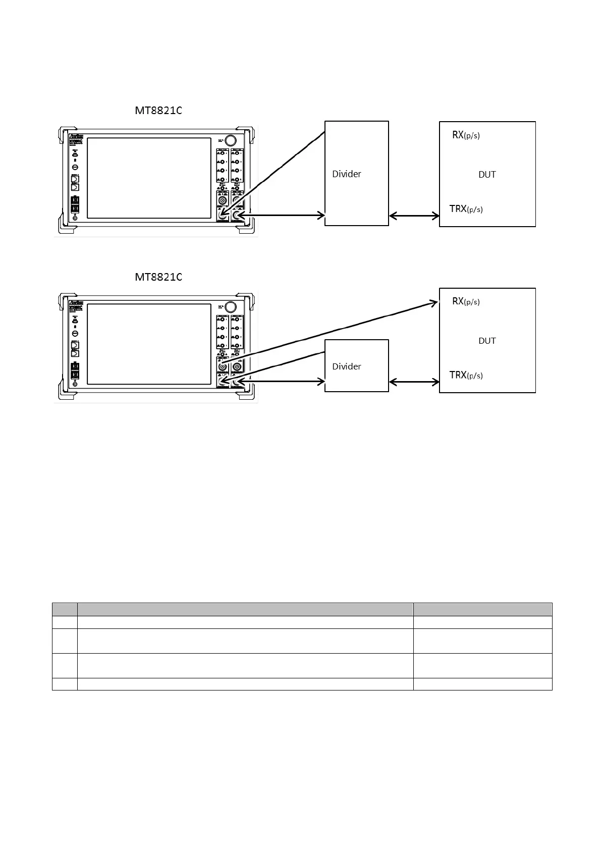
Figure 3.7.3-1 Connection Diagram of SCC UL Throughput (DL SISO)
Figure 3.7.3-2 Connection Diagram of SCC UL Throughput (DL MIMO)
NOTE :
Input the PCC and SCC– 1 uplink signal to both of Phone1 and 2.
For DL MIMO, connect the input and output of Phone2 to different terminals.
UL Throughput Measurement 3.7.4.
This chapter describes the procedure for this method.
Example: FDD DL 3CA MIMO / UL 2CA
3.7.4.1. Parameter settings
Load LTE software at Phone1 and 2.
Perform Preset Enter Sync at Phone 1.
Refer to 3.1 Preset Enter Sync (v30.10).
Set to Main2 at Phone2 DL terminal so MT8821C receives SCC-1 uplink signal
by Main1.
Set the following parameters.