264
B.2. Carrier Leakage Frequency
This chapter explains the carrier leakage frequency setting for MT8821C intra-band contiguous component carrier
(CC) measurement.
To remove the effects of carrier leakage and correctly measure Transmit Modulation for CA (EVM, Carrier Leakage
and In-band Emissions) as specified in 3GPP TS36.521-1 6.5.2A, the carrier leakage position must be first configured
accordingly before performing intra-band contiguous CC measurements. This is done by setting the TX
Measurement - Carrier Leakage Frequency parameter.
B.2.1. Transmitter LO Configuration
For LTE Uplink CA transmission, different UE transmitter RF reference architectures are described in 3GPP TR36.807
Figure 6.1-1. The UE transmitter may either employ a single-LO or a two-LO architecture.
The carrier leakage position varies, depending on the UE transmitter architectue and channel bandwidth
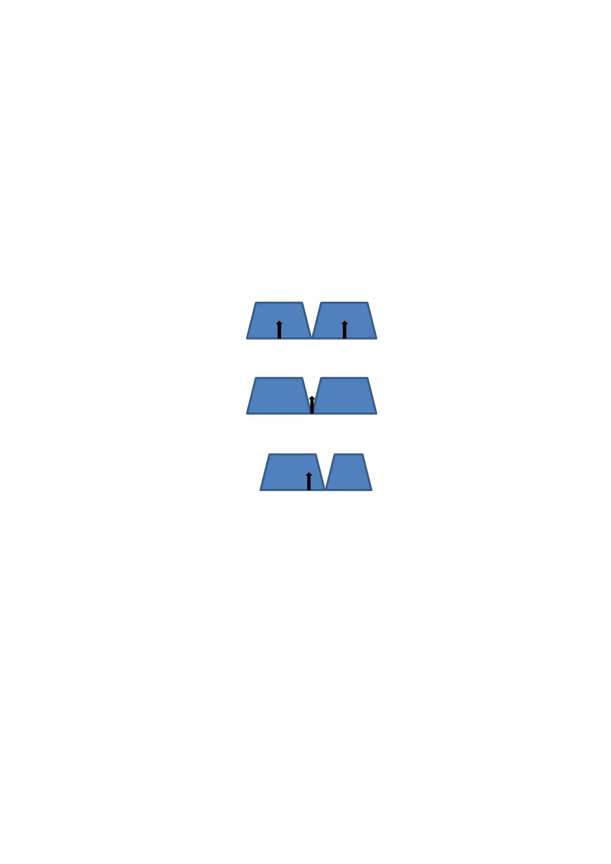
configuration of each CC. The figure below shows three possible carrier leakage positions for intra-band
contiguous CC transmission.
(a) Two-LO Architecture, Non-equal or Equal UL CC Channel BW
(b) Single-LO Architecture, Equal UL CC Channel BW
(c) Single-LO Architecture, Non-equal UL CC Channel BW
Fig. B.2.1-1. Possible Carrier Leakage Positions
Figure B.2.1-1 (a) shows the carrier leakage for the two-LO architecture where the carrier leakage is at the center of
each CC. Figure B.2.1-1 (b) and (c) shows the possible carrier leakage positions for the single-LO architecture
wherein the carrier leakage is on the center of the Aggregated Transmission Bandwidth Configuration. For the case
of equal bandwidth configuration (b), the carrier leakage falls in between the two CC’s. However, in the case of
non-equal bandwidth configuration (c), the carrier leakage falls at the CC with the wider channel bandwidth.