1-16
AX-4030
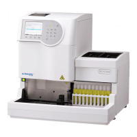
AUTION MAX AX-4030 OPERATING MANUAL
D
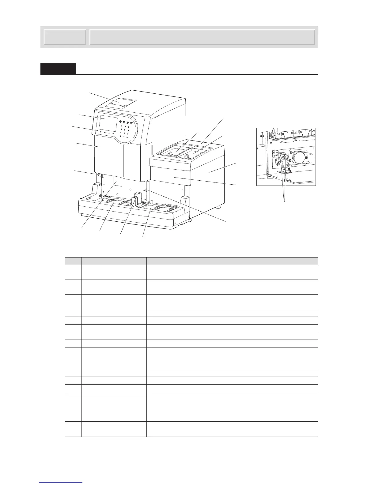
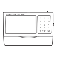
1.3.1 Front View
No. Components Descriptions
1 Standby switch Use this switch to turn on and off the instrument for daily use. The
switch lamp illuminates green while the power is on.
2 Front cover This protects the nozzle drive unit and prevents users from accidentally
touching the nozzle.
3 Operator panel There are operation keys for starting measurement and entering
numeric values. See
“1.7 Basic Operations” on page 1-40.
4 Display You can view results and check status information here.
5 Built-in printer This thermal printer prints results and parameter settings.
6 Feeder protective cover This cover protects two feeders.
7 Feeder cover 1 This cover has a locking lever to open and close feeder 1.
8 Feeder cover 2 This cover has a locking lever to open and close feeder 2.
9 Side cover The pumps for aspirating samples, for staining samples on test strips,
and for flushing the washing solution are located inside. The trap bottle
is also attached here.
10 Maintenance cover Open this cover to clean inside the instrument.
11 Loading side Place sample racks with samples loaded here.
12 STAT port Load a sample for port STAT measurement here.
13 Unloading side The sample racks are discharged here after sample aspiration. If the
instrument has been set for loop transportation, you can load 5 more
sample racks to be measured here.
14 White plate cover Open this cover to replace the white plate.
15 Built-in barcode reader The barcode reader reads barcodes labeled on sample tubes.
16 Drain pinch valves These valves control drainage flow.