AX-4030
1-17
AUTION MAX AX-4030 OPERATING MANUAL
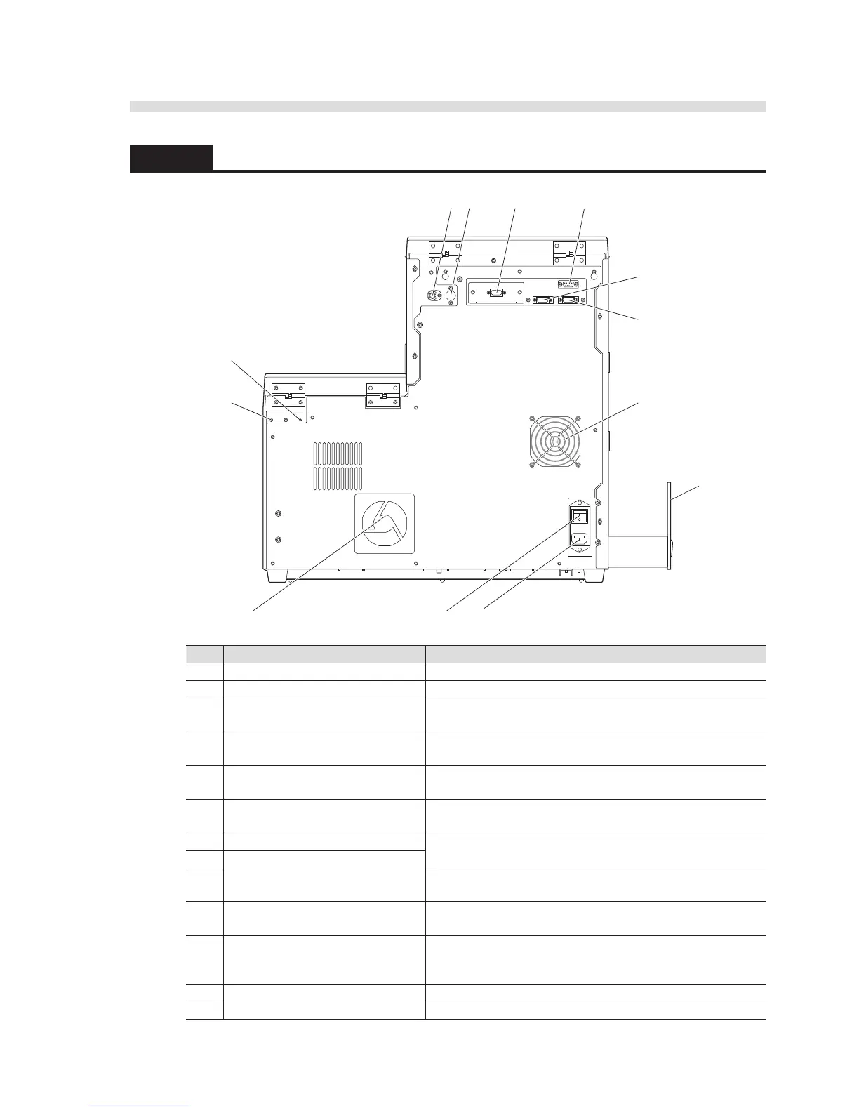
1.3.2 Rear View
No. Components Descriptions
1 Drain joint (D) Connect the tube from the drain bottle here.
2 Washing solution joint (W) Connect the tube from the washing solution bottle here.
3 Washing solution sensor terminal
(S)
Connect the liquid sensor cord of the washing solution bottle
here.
4 Hand-held barcode reader terminal
(H)
Connect the optional hand-held barcode reader here.
5 Data output terminal (P)* Connect the communication cable from an RS-232C port of
an external device here.
6 Data output terminal (E) Connect the communication cable from an RS-232C port of
the AX-4030-exclusive device here.
7 START terminal (1) Use these terminals to attach the extended sampler or joining
unit A.
8 STOCK terminal (2)
9 Cooling fan The fan exhausts heated air to keep the inside of the
instrument cool.
10 Cooling fan The fan draws in air from outside to cool the inside of the
instrument.
11 Main power switch Press this switch to turn on or off the main power supply.
Keep this switch on for daily use, and turn it off when cleaning
specific components or during long-term disuse.
12 Power input terminal Connect the power cord which came with the instrument here.
13 Waste box tray Attach the waste box here to collect used test strips.
* This terminal can be replaced with the Ethernet terminal (optional Ethernet board) to connect the instrument to a LAN.
For more information, contact your distributor.