186 CONFIGURA TION
CONFIGURATION 2
DIGIT AL OUTPU TS 3
DIGIT AL OUTPU TS 3
DOP3 (T 24) SETUP 4
DIGIT AL OUTPU TS 3
DOP1 (T 22) SETUP 4
DIGIT AL OUTPU TS 3
DOP2 (T 23) SETUP 4
DIGIT AL OUTPU TS 3
DOP1 (T 22) SETUP 4
DOP1 (T 22) SETUP 4
GET FROM
DOP1 (T 22) SETUP 4
261)DOP1 RECTIFY EN
DOP1 (T 22) SETUP 4
262)DOP1 THRESH OLD
DOP1 (T 22) SETUP 4
263)DOP1 IN VERT M ODE
13.6.1.8 DIO X SETUP / DIO1/2/3/4 Input low value PINs 276 / 282 / 28 8 / 294
See 13.6.1.6 DIO X SETUP / DIO1/2/3/4 Make input GOT O destination connection.
Note. You can make a simple OR gate by selecting this as the target PIN of a logical GO TO.
13.6.1.9 Default connections for DIO 1/2/3/4
DIOX Terminal Function Terminal IO mode High value Low value G OT O
DIO1 Zero reference interlock T18 Input 0.01% (High) 0.00 % (Low) PIN 116
DIO2 Jog Mode select T19 Input 0.0 1% (High) 0.00 % (Low) PIN 42
DIO3 Ramp Hold T20 Input 0.01% (High) 0.00% (Low) PIN 33
DIO4 Dual current clamp enable T21 Input 0.0 1% (High) 0.00 % (Low) PIN 88
13.6.1.10 DIO1/2/3/4 Internal output result PINs 6 85/6/7/8
There is a hidden PIN for each block to enable internal connection of the output processing part of the block.
This section of the block will continue to function irrespective of the output mode.
DIO 1/2/3/4 PIN 685/6/7/8)DIO 1 O/P BIN V AL.
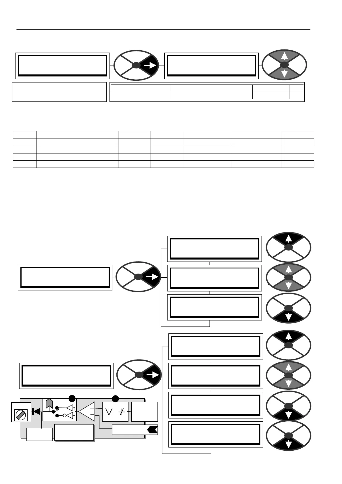
13.7 CONFIGURATION / DIGITAL OUTPUTS
PINs used 261 to 269.
There are 3 digital outputs DOP1/2/3.
See 3.4.2 Digital inputs and outputs
(D OP3 may be used to control external serial link
convertors.)
13.7.1 DIGIT AL OUTPUTS / DOPX SETUP
The windo ws are shown for DOP1. DOP2/3
windo ws are identical apart from the PIN numbers.
DIO1 (T 18) SETUP 4
276)DIOX IP LO V ALUE
276)DIOX IP LO V ALUE
0.00%
PARA METER RANGE DEF AULT PIN
DIO 1 IP LO V ALUE + /- 300.00% 0.00 % 276
Sets the level of the value
selected by a low DIOX input.
DOP1 Digital
OP terminal
DOP1
GET FRO M
PIN 262 Threshold
PIN 261
Rect/Bipolar
T 2 2
PIN 263
PIN
68 2
DOP monitor
PIN 16 4