CONFIGURA TION 187
DOP1 Digital
OP terminal
DOP1
GET FRO M
PIN 262 Threshold
PIN 261
Rect/Bipolar
T 2 2
PIN 263
PIN
68 2
DOP monitor
PIN 16 4
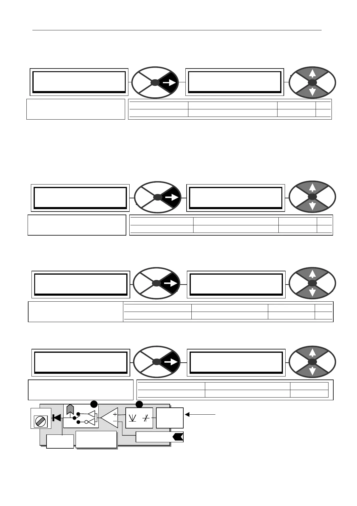
13.7.1.1 D OPX SETUP / DOP1/2/3 OP val rectifiy enable PINs 261 / 26 4 / 267
The digital output is generated by comparing an internal linear or logic signal with a threshold.
Select DISABLED for the bi-polar mode.
E.g. Linear speed feedback. The rectified mode will enable the digital output to change state at a chosen
speed for both directions of rotation. The bipolar mode will enable the digital output to change state at only
one chosen point in the entire range of positive or negative rotation.
13.7.1.2 DOPX SETUP / DOP1/2/3 OP comparator threshold PINs 262 / 2 65 / 268
The output of the comparator will be high w hen the signal from the rectifier mode box exceeds the threshold.
The comparator output is lo w for identical inputs.
13.7.1.3 D OPX SETUP / DOP1/2/3 Output inversion enable PINs 263 / 266 / 269
13.7.1.4 DOPX SETUP / DOP1/2/3 Make output GET FROM source connection
The connection is made here for the digital output
block source. It may be a linear or logic value. After
processing by the rectifier box it gets compared to
the threshold. The comparator output state HIGH or
LOW is then inverted or not inverted by the inverter
mode box and becomes a 24 V logic signal.
For comparing logic values alw ays put 0.00% in the threshold windo w. The comparator output is low for
identical inputs.
DOP1 (T 22) SETUP 4
261)DOP1 RECTIFY EN
261)DOP1 RECTIFY EN
ENABLED
PARA METER RA NGE DEFAULT PIN
DOP1 RECTIFY EN EN ABLED or DIS ABLED ENABLED 261
Enables rectified mode for the
OP generator.
DOP1 (T 22) SETUP 4
262)DOP1 THRESH OLD
262)DOP1 THRESH OLD
0.00%
PARA METER RANGE DEF AULT PIN
DOP1 THRESHOLD + /- 300.00% 0.00 % 262
Sets the comparator threshold
for the DOPX OP generator.
DOP1 (T 22) SETUP 4
263)DOP1 IN VERT M ODE
263)DOP1 IN VERT M ODE
NON-IN VERT
PARA METER RAN GE DEFA ULT PIN
DOP1 IN VERT MODE IN VERT or NON-INVERT NON-IN VERT 263
Allo ws the comparator output
logic to be inverted for DOPX
DOP1 (T 22) SETUP 4
GET FROM
GET FROM
PIN) Description of function
PARA METER RANGE DEF AULT
GET FROM PIN 000 to 720 400
Defines the source PIN for the
connection to DOPX OP