188 CONFIGURA TION
CONFIGURATION 2
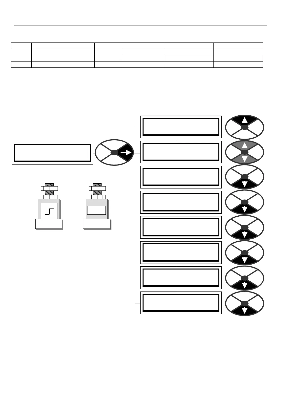
ST A GING POSTS 3
ST A GING POSTS 3
303)ANALO G POST 4
ST A GING POSTS 3
296)DIGIT AL POST 1
ST A GING POSTS 3
297)DIGIT AL POST 2
ST A GING POSTS 3
298)DIGIT AL POST 3
ST A GING POSTS 3
299)DIGIT AL POST 4
ST A GING POSTS 3
300)ANALO G POST 1
ST A GING POSTS 3
301)ANALO G POST 2
ST A GING POSTS 3
302)ANALO G POST 3
13.7.1.5 Default connections for DOP1/2/3
DOPX Terminal Function Terminal Threshold Getfrom source GET FRO M Pin
DOP1 Zero speed T22 0.00 % (Low) Zero speed flag PIN 120
DOP2 Ramping flag T23 0.00 % (Lo w) Ramping flag PIN 35
DOP3 Drive healthy T24 0.00 % (Low) Drive healthy flag PIN 698
13.7.1.6 D OP1/2/3 Internal output result PINs 682/3/4
The binary result of these outputs is available for internal use on PINs 682 DOP1, 683 DOP2, 684 DOP3.
13.8 CONFIGURATION / STAGING POSTS
PIN number range 296 to 303.
These staging posts are like virtual wire wrap
posts.
There are 4 digital posts and 4 analogue posts.
The digital and analogue posts are allocated PIN
numbers and are used as virtual wiring nodes.
They can contain a value or act as constants for
setting a value.
1) When receiving values via a serial link, the
posts can store the data and are then connected
by the user to the desired destinations.
2) Blocks in the applications menu are normally
dormant. Connecting the output to a PIN
destination other than 400 activates them. Using
a soft w are post is extremely useful during system
commissioning if a block output needs to be
examined prior to incorporation into a system. The block output will be activated by connecting it to one of
these posts. It may then be monitored via the display, and if required, connection to an analogue output
terminal using the terminals GET FROM link allo ws monitoring with an oscilloscope. See also 13.4.3
ANALO G OUTPUTS / Scope output select PIN 260. When satisfied with the output functionality, you can
then connect it to the final system destination.The analogue posts are used for linear values.
The digital posts are used for logic values, a zero value is a logic low, a non zero + /- value is a logic high.
Note. Staging posts are also used for making connections between a GOTO and a GETFRO M.
Note. Any unused settable PIN may perform the function of a staging post. A convenient cluster of 8 PINs
can be found in the PRESET SPEED application block for example.
HIGH
LO W
DIGIT A L POST1
PIN 2 96
0.0 0 %
ANAL O G PO ST1
PIN 3 00