CONFIGURA TION 185
13.6.1.5 DIO X SETUP / DIO 1/2/3/4 Make output GET FROM source connection
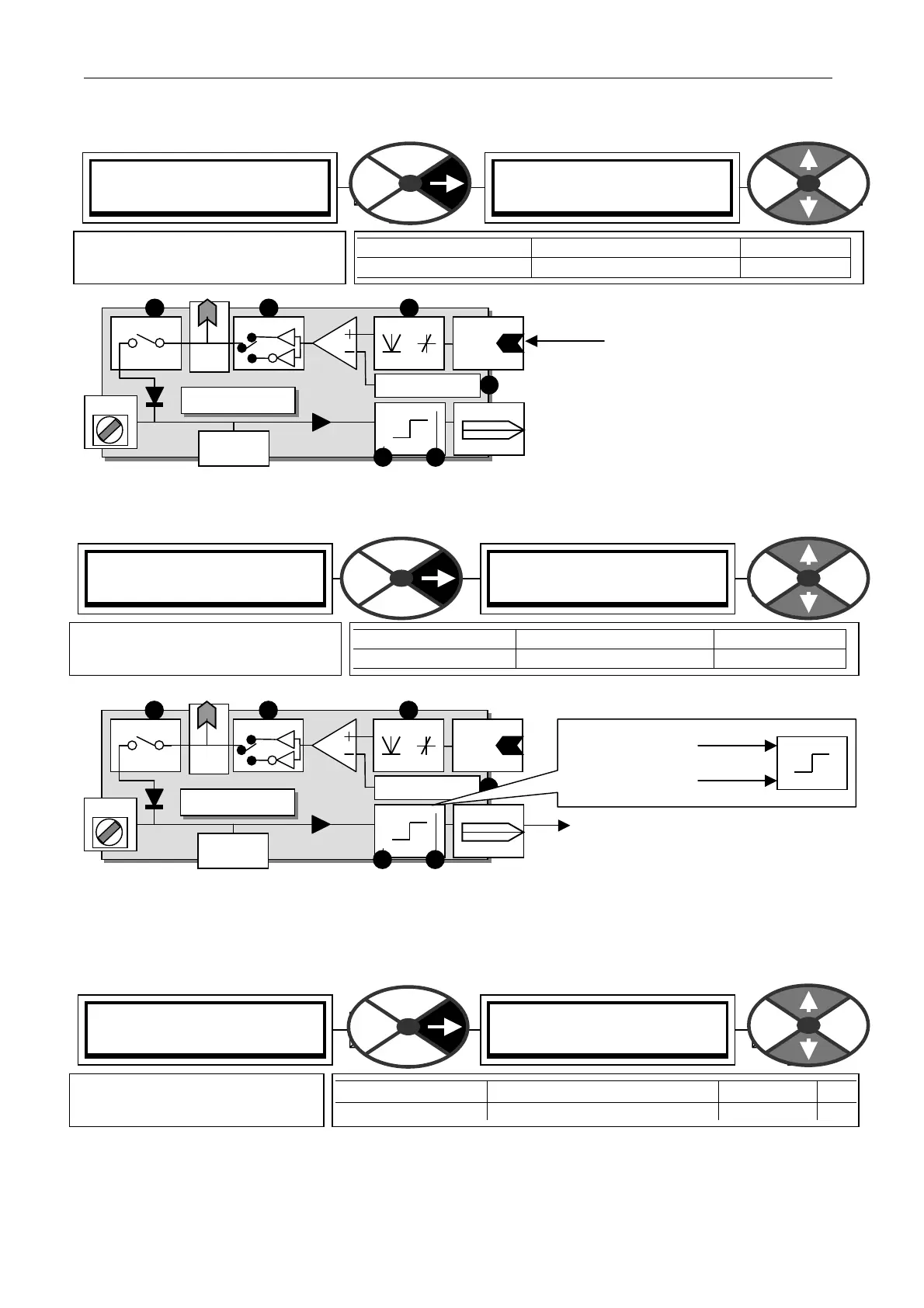
The connection is made here for the digital
output block source. It may be a linear or logic
value. After processing by the rectifier box it
gets compared to the threshold. The
comparator output state HIGH or LOW is then
inverted or not inverted by the inverter mode
box. It then proceeds to the output stage
through the digital output enable switch and
becomes a 24V logic signal. It is also available
for internal connection. See 3.4.2 Digital inputs and outputs.
13.6.1.6 DIO X SETUP / DIO1/2/3/4 Make input G OT O destination connection
The digital input mode detects whether the input is high or low, and then selects an output value
The connection is made here for the digital
input LO or HI result GOTO destination.
The LO and HI values can be entered using the
display and keys. To switch dynamically
changing values, connect them using jumpers to the LO/HI value PINS. For logic only usage a value of 0.00%
is read as a low. Any non zero + /- value is read as a high. Logic inversion is accomplished by entering
0.00% in the value for HI windo w and 0.01% in the value for LO windo w.
13.6.1.7 DIO X SETUP / DIO 1/2/3/4 Input high value PINs 275 / 28 1 / 287 / 2 93
See 13.6.1.6 DIO X SETUP / DIO1/2/3/4 Make input GOT O destination connection.
Note. You can make a simple A ND gate by selecting this as the target PIN of a logical GOTO.
DIO1 Di
ital IO
DIO 1
High value
Low value
GO TO
DIO 1
GET FRO M
PIN 272
Rect/Bipolar
PIN 271
OP mode en
PIN 275
PIN 276
T 1 8
PIN 274
PIN 273 Threshold
PIN
68 5
DIO Monitor
PIN 163
DIO1 Di
ital IO
DIO 1
High value
Low value
GO TO
DIO1
GET FRO M
PIN 272
Rect/Bipolar
PIN 271
OP mode en
PIN 275
PIN 276
T 1 8
PIN 274
PIN 273 Threshold
PIN
68 5
DIO Monitor
PIN 163
If the input is high then the
HI value is selected.
If the input is lo w then the
LO value is selected.
PIN X X X
PIN X X X
DIO1 (T 18) SETUP 4
GET FROM
GET FROM
PIN) Description of function
PARA METER RANGE DEFAULT
GET FROM PIN 000 to 720 400
Defines the target source PIN for
connection to the DIO X.
DIO1 (T 18) SETUP 4
GO TO
GO TO
PIN) Description of function
PARA METER RANGE DEF A ULT
GO TO PIN 000 to 720 See 13.6.1.9
Defines the target destination PIN
for connection to the DIOX.
DIO1 SETUP 4
275)DIO1 IP HI V ALUE
275)DIO1 IP HI V ALUE
0.01%
PARA METER RA NGE DEFAULT PIN
DIO 1 IP HI V ALUE + /- 300.00 % 0.01% 275
Sets the level of the value
selected by a high DIO X input.