Chapter 3: Theory
3/10
Operators & Maintenance Manual GENIUS Compact Version UK 0.1 © BESTnv
BESTnv Industrial Research BV, Marinus van Meelweg 20, 5657 EN, EINDHOVEN, THE NETHERLANDS
General tel. +31 (40) 292 2622 - Service tel. +31 (40) 292 2620 - Fax. +31 (40) 292 2633 - Email: service.BESTnv@bestnv.com
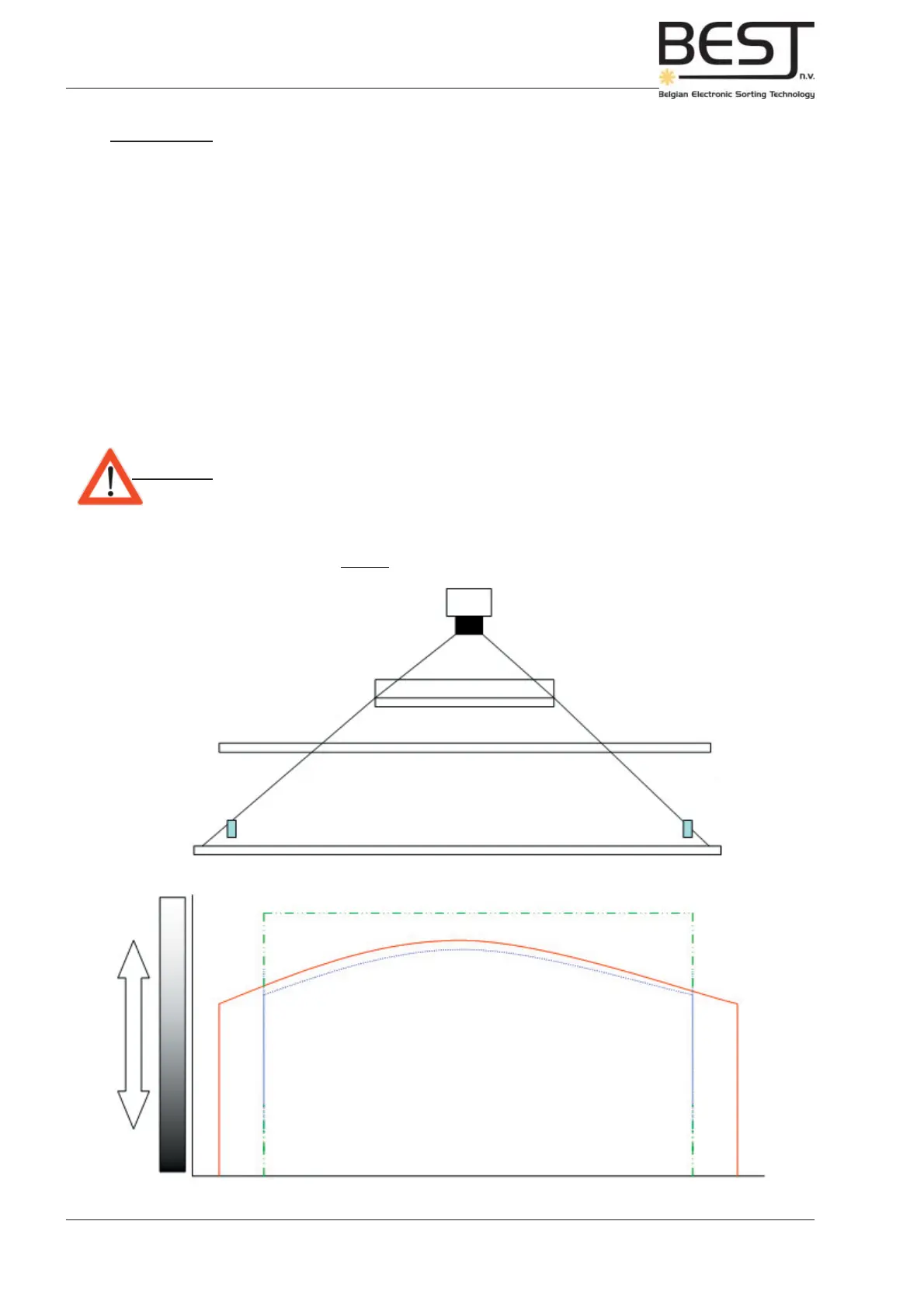
Picture: Normalization theory
Camera
2048 pixels
Mirror
Illumination:
HF-lights or LED-lighting
Product
guidance strip
Belt
255
White
Black
1 PIXEL 2048 PIXELS
Normalized signal
Normalization signal
or Reference Line
Camera
signal
0
Normalization
The Reference Line is in fact simply the signal you get when scanning the empty and clean detection belt.
An unprocessed camera signal of a belt with products does not generate a continuous straight line as
could be expected, but a rather unevenly curved line (see picture underneath). This is due to different
limitations of the optical setup: irregularities in the belt surface, local variations in the illumination, uneven
distance to belt surface, etc...
To create a straight line with only clear dips and peaks for the defects and products, the reference line
(B) is used to correct all unprocessed camera signals (A). The resulting signals (C) can be used to sort
the product by adding one or more different thresholds.
It is of course very important that the reference line corresponds to the actual condition of the belt. If the
belt is dirty or damaged, or the lighting has changed since the reference line was last taken (new lamps
or reference line has been made too long ago), then the image of he reference line will no longer be
accurate, and this will cause false detections and certainly decrease the effi ciency of the sorter.
Attention: - Whenever the sorter is started up a new Reference Line/Normalization
should be taken before starting the sorting process.
For more practical info on taking this reference line, see chapter 5: Operational procedures.