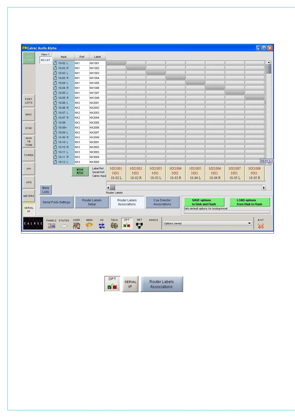
The input ports are shown down the left
hand side of the screen, and the Router
labels are shown along the bottom
of the screen. This forms a grid, and
associations are made by selecting the
intersecting cell between input port and
router label. Each leg of the input ports
is always presented as if it were a mono
port.
When an association is made, the cell will
turn yellow. Associations can be unmade
by selecting the cell again, whereby its
colour will change back to grey. The +1
ROUTER LAbEL ASSOCIATION SCREEN
button is used to automatically move
diagonally down the grid to the next
association cell and toggle its condition.
The action occurs out of sight even if
you go beyond the viewed section of the
screen.
Once an input port is associated with a
Router label, the labels will be visible on
the fader label column on the I/O - Input
screen on whichever channel the port is
patched. If a new fader label is entered
on the I/O - Input screen, it overrides the
router label. The router label will also be
displayed on the channel display on the
fader module.
If the Router fails to communicate for
longer than ten seconds then the Router
label text is cleared and the fader labels
revert back to displaying the input port
label.