LIVE MEMORY
1 2 3
4 5 6
7 98
0
CLR EXEC
> <
LOAD
PRE
VIEW
SAVE
MY4883
1 2
I/O MATRIX
A
<
B
>
>>
< >
INPUT
MEMORY
INSERT
KEY
DIRECT O/P
PORT/No.
GROUP
SURR
STEREO
CHANNEL
MONO
ON
I/P LABEL
FADER
EXEC
SEL
MEM
SEL
FADER
SELECTED MEMORY
INSERT
INTO
REMOVE
STACK
MOVE PATH
PORT
1
PORT
2
TO
FADER
FDR19A
Drums M 23LR
04 08 76
04
Scene8
Scene3
SEL PORT/No.PATH TYPE
IU5472
Pres 1
SL
SL
ST
ST
MR
MR
SS
SS
AFL
T
ON
CUT
GP
GP
60
50
40
30
20
10
5
0
10
5
M/S
EQ
DYN
PEAK
PFL
DYN
O/P
I/P
E
C
8
12
16
20
24
4
48
FLTR
8
Mic 1
A
B
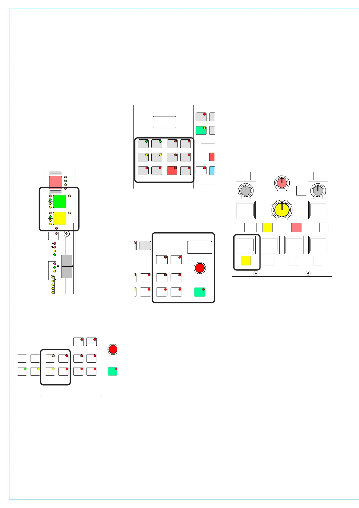
As a safety measure, ensure that all faders
are minimized, and the control room level
control is no more than half way up.
Check that the basic system ports have
been set up and the control room monitor
speakers are connected to the appropriate
outputs. Then, choose a channel fader
by pressing the A (or B) button on the
channel fader panel.
Next, go to the I/O Matrix panel and, if a
path type is not already indicated, press
either the mono or stereo buttons to
assign a mono, stereo or 5.1 surround
channel to the fader.
gETTINg STARTED
Next, go to the Input/Output panel and
select Input 1.
Return to the I/O Matrix panel and also
select Input 1 in order to assign a port to
it. Do this by turning the selector control
knob to scroll through the available ports.
Pressing the knob down and turning it
will switch to another list of input ports
(providing these have been set up on the
Options - Port List screens). Once you
have arrived at the port you want, press
the ON button to connect it. (this is like
inserting the patch cord).
Set the input gain, panning, etc, on the
Input/Output panel, the EQ and Dynamics
on their respective panels, and route the
<< >>
LB RB
OL
/ /
OR
2
48L 48R
TONE M/S
IN
EQ
PRE
EQ
PRE
BUS
TONE
TB
MIX
MINUS
IN IN
GAIN
INPUT SELECTION
STEREO WIDTH
FRONT/BACK PAN REAR PAN DIVERGENCE
FRONT PAN
BALANCE
DIRECT OUTPUT
SURROUND SOUND
ININ
REAR
LEVEL
1
LFE
L-C-R
ON
INPUT
INSERT
FDR
PRE
FDR
PRE
INPUT
PY4885
OUTPUT
DIRECT OUTPUT
AFL
SRC
MAIN
GP
DIRECT
C
ONLY
- 9.0 dB LS >RS - 7.5 dB L 4 R
FDR19A
Drums
- 4.6 dB
+56.0 dB
MIC L R M S >W L C >R
5.0
LEVEL
IN
AUTO
FDR
signal, to Main 1 say, on the Routing
panel.
Now fade up the Main 1 fader and select
Main 1 SURR as a Control Room Pre-
Select (Monitor LS panel), and press
HEAR. If the channel fader and LS
controls are set correctly you should hear
the signal.
Refer to the descriptions of the individual
control panels and screens for more
detailed descriptions.
LIVE MEMORY
1 2 3
4 5 6
7 98
0
CLR EXEC
> <
LOAD
PRE
VIEW
SAVE
MY4883
1 2
I/O MATRIX
A
<
B
>
>>
< >
INPUT
MEMORY
INSERT
KEY
DIRECT O/P
PORT/No.
GROUP
SURR
STEREO
CHANNEL
MONO
ON
I/P LABEL
FADER
EXEC
SEL
MEM
SEL
FADER
SELECTED MEMORY
INSERT
INTO
REMOVE
STACK
MOVE PATH
PORT
1
PORT
2
TO
FADER
FDR19A
Drums M 23LR
04 08 76
04
Scene8
Scene3
SEL PORT/No.PATH TYPE
MP5405
SMALL LS
LEVEL
L R
BALANCE
DIM
CLEAR
DIRECT
INPUT
CH ANGE
OVER
S TE RE O
MONO
SURR
MAIN 1
MISC OP5
STEREO
MAIN 1
MISC OP6
PFL
MISC OP4
STEREO
MAIN 1
MISC OP1
SURR
MAIN 1
MISC OP2
SURR
MAIN 1
PRE-SEL1
LS RS
LFE OFF
L C R
MISC FUNCTIONS
SURR
MAIN 2
PRE-SEL2
STEREO
VTR1/1
PRE-SEL3
AUX 3
PRE-SEL4
IN
LS MON
INSERT
NO COMP
FULL
DP570
DECODERS
DIM
CUT
MUTE
CR MON
FOLLOW
MISC OP3
MUTE MUTE MUTE
MUTE MUTE
0
PFL/LIST AFL
CONTROL
ROOM
MONITOR
1 2
3 4
5 6
0
1
HEAR
2
HEAR
3
HEAR
4
INPUT
DIRECT
HEAR