CALREC Putting Sound in the Picture 129
SDI INPUTS
Each SDI input stream has the capacity to
carry 16 mono legs of audio and these are
configured as though 8 AES stereo pairs.
This makes for a total of 32 AES pairs (64
mono legs).
Whilst the incoming digital audio may
often be synchronous with the console
reference, sample rate converters are
always in the signal path to ensure digital
sync is never an issue.
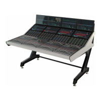
Signals are patched to desk channels in
a similar fashion to those from all other
types of inputs. The significant difference
is that unlike other Hydra input boxes that
allow ports to be named in the console
software, SDI inputs use a fixed name
structure of the form:
1S--B1
The first digit identifies the box number,
and up to 9 SDI boxes can be used on a
network.
In the image below, the B following
S-- indicates that this signal is coming
from SDI input stream 2 (stream 1 being
labelled ‘A’). The 1 shows that this signal is
the first AES pair on that SDI stream.
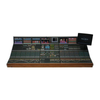
When the optional Dolby E decoders
are installed, an extra level of patching is
required to assign decoders to the AES
pairs that have been decoded from the
SDI streams.
Select the incoming AES pair carrying the
encoded signal, choose an available Dolby
E decoder and select PATCH. Dolby E can
carry up to 8 legs of audio per AES pair so
each Dolby decoder extracts four pairs of
signals.
In the example above, Dolby decoder A
in SDI box number 1 has received the 1st
AES pair from SDI stream 3; the signal
referred to as 1SDI31.
At the decoder outputs, this example
shows the first of the four decoded signal
pairs being known as:
1S31A1
The ‘DI’ parts of the original name now
take on the stream and pair indication.
The A shows it is decoder A and the 1,
that it is the first decoded signal pair.
These are the pairs that appear as
sources in the normal I/O patching
system.
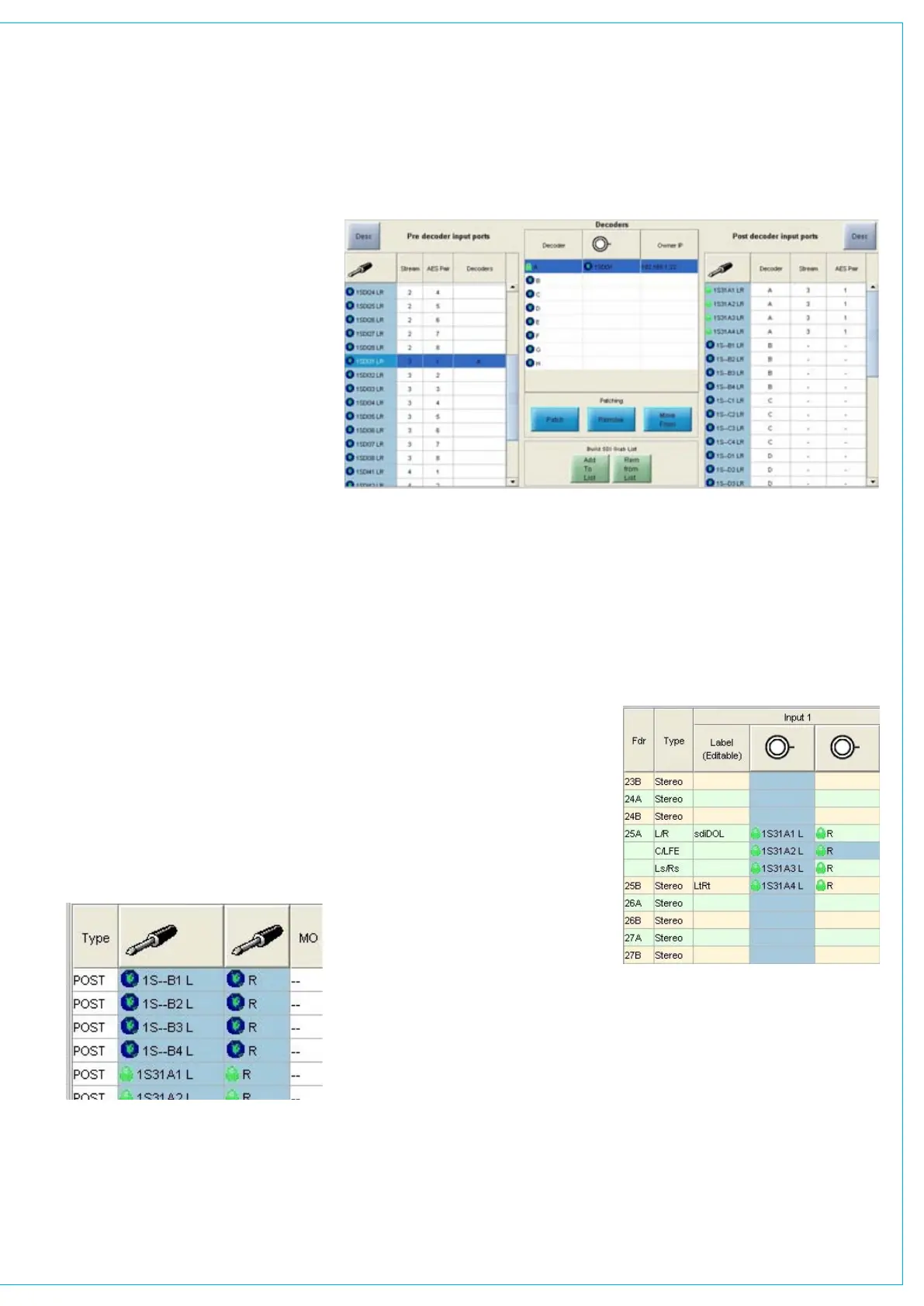
It is likely that customers will have defined
a usage for streams and pairs within SDI
signals and for Dolby E encoded signal
pairs within the SDI pairs. A possible input
patch scenario is the one shown below
where the surround channel on fader 25A
carries signals decoded from three Dolby
E pairs and the stereo channel on fader
25B carries an LtRt version of the same
signal.