CALREC Putting Sound in the Picture 13
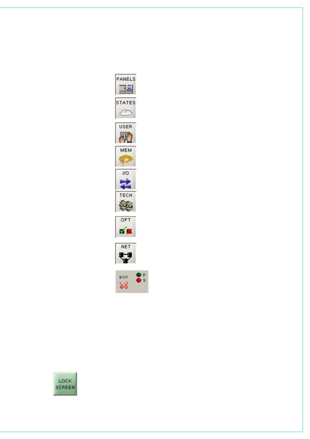
TOUCH SCREEN LAyOUT
The Front End screens are divided into
groups which are accessed using the
buttons along the bottom of the display.
Within each group there are a number of
screens accessed by buttons up the left
side of the display. On some screens,
there are additional buttons to access
sub-sets of the screen’s function.
Options Settings
Options settings are not stored in the
individual console memories but are saved
and loaded separately using the buttons on
each Options screen. This allows changes
to be made without invalidating any saved
memories. Changes to options take effect
as soon as they are made, however if they
are not saved, the next time the desk boots
up the options will revert to their previous
settings. Upon loading the options settings
from the file on the hard disk, any changes
made will be over-written unless they have
been saved. This allows changes to be tried
out without losing the original settings and
these original settings can be restored
without having to re-boot the system.
Second PC screen
The software now supports use of a
second PC screen which is configured as
a Windows ‘extended desktop’. Any of the
screens showing a LOCK SCREEN button
can be sent to that second monitor by
pressing the button. They will remain on the
second monitor whilst the main monitor is
reassigned to any other required functions.
Operational reproductions of the EQ, Dynamics, Routing,
Aux Send, Aux Output and Delay panels; providing alternative
controls.
Sets the current state of various functions (these are not
stored with the user memories or options - only in the live
(hidden) memory.)
Operational screens which enhance the controls on the
console and for setting options which are stored with the user
memories.
Memory control screens to supplement the panel controls.
Set up and display of all the I/O connections stored
with the user memories.
Entry to and control of password-protected operational
modes, troubleshooting screens.
The options screens are used to preset the system to
the studio’s required settings. Includes set up of meter
configurations, monitor panel configurations, serial interface
and label associations, GPIO and condition switching.
Screens for setup and control of a Hydra audio network system
These screens are only visible if Hydra audio networking is
installed.
The “EXIT” button at the bottom corner of the screen will
exit the application.
Next to this button are two indicators which show the status
of the primary and secondary control processors. During
normal operation, the primary processor will be in use, and its
indicator will be green. When busy the processor’s indicator
will be yellow, during which time no changes can be made to
the control screens (changes to the control surface can be
made, and will take immediate effect). Whilst the secondary
processor is in standby, (ready to take over from the primary
should a fault develop), its indicator will be amber. If the primary
processor fails, its indicator will change to red. The secondary
processor will take over, and its indicator will change to green.
When the primary processor becomes available again, it will
automatically take back control from the secondary processor,
and the secondary processor will return to standby mode.