CALREC Putting Sound in the Picture 67
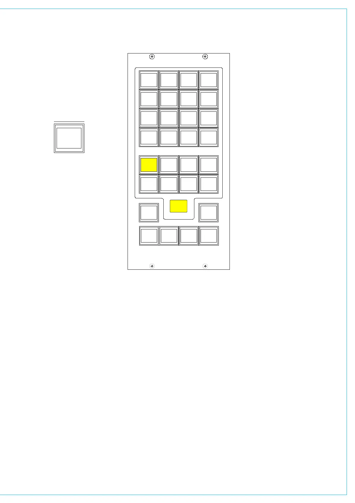
The different types of decoder are
located in separate banks, and functions
are chosen in the same way as monitor
sources.
The decoder function buttons are as
follows:
1 button for Pro Logic mode. When
using a Dolby DP570, it is assumed that
it will be set to Dolby Digital mode either
in manual or auto detect mode.
3 buttons for Alternate Compression
Modes: CUSTOM, LINE and RF. If
none are selected, there will be
no compression and no dialogue
normalisation.
4 buttons for Alternate Output Modes:
PHAN CENTRE, 3 STEREO, STEREO
and MONO. If none are selected, the
output will be full surround.
When controlling a Dolby SDU4, LT/
RT decoder, only the stereo and mono
output mode buttons will function.
MY5403
MONITOR SEL
PRO
LOGIC
ASSIGNMENT
SELECTION TYPE
SELECTION
CUSTOM
DECODERS
DP570
LINE RF
PHAN
CENTRE
MONO
SDU4
3
STEREO
STEREO
SURR
MAIN 1
METER 1
CR MON
FOLLOW
METER 2
SURR
MAIN 2
METER 3 METER 4
STEREO
EXT 1
MP5405
SMALL LS
LEVEL
L R
BALANCE
DIM
CLEAR
DIRECT
INPUT
CHANGE
OVER
STEREO
MONO
SURR
MAIN 1
MISC OP5
STEREO
MAIN 1
MISC OP6
PFL
MISC OP4
STEREO
MAIN 1
MISC OP1
SURR
MAIN 1
MISC OP2
SURR
MAIN 1
PRE-SEL1
LS RS
LFE OFF
L C R
MISC FUNCTIONS
SURR
MAIN 2
PRE-SEL2
STEREO
VTR1/1
PRE-SEL3
AUX 3
PRE-SEL4
IN
LS MON
INSERT
NO COMP
FULL
DP570
DECODERS
DIM
CUT
MUTE
CR MON
FOLLOW
MISC OP3
MUTE MUTE MUTE
MUTE MUTE
0
PFL/LIST AFL
CONTROL
ROOM
MONITOR
1 2
3 4
5 6
0
1
HEAR
2
HEAR
3
HEAR
4
INPUT
DIRECT
HEAR
DECODER REMOTES
Dolby DP570 & DP564 Setup
These notes are offered for guidance
only and relate to firmware versions
in use around 2006. Other issues of
Dolby firmware may require a different
procedure and always consult the Dolby
supplied documentation.
On the Dolby unit:
<label> means press the button with the
name label.
Power up the unit.
<setup>
<down arrow> until you see “SYSTEM
SETTINGS”
<enter> Unit name is now displayed
<down arrow> until you see “GPI
setup”
<enter> “GPI pin 23” is displayed
<enter> “GPI pin 23 trigger” is displayed
<enter>
<down arrow> until you see “Edge”
<enter>
<esc> “GPI pin 23 trigger” is displayed
<down arrow> “GPI pin 23 Polarity” is
displayed
<enter>
<down arrow> until you see “Positive/
High”
<enter>
<esc> “GPI pin 23 Polarity” is displayed
<down arrow> “GPI pin 23 Function” is
displayed
<enter>
<down arrow> until you see “FULL”
meaning surround.
<enter>
<esc> “GPI pin 23 Function” is displayed
<esc> “GPI pin 23” is displayed
<down arrow> “GPI pin 24” is displayed
Repeat the process for all the GPI pins 24
- 31 (as drawing/spreadsheet 0681-87)
<esc> “GPI setup” is displayed
<down arrow> “GPO setup” is displayed
Now go though the same routine to set up
the outputs on pins 7 to 14 (as drawing/
spreadsheet) with trigger as “Level”,
Polarity as “Positive/High”, and function
as spreadsheet.
<esc> Until back at original menu.
Note: With issue 1 cable, the outputs are
on pins 8 to 15.