138 A L P H A with Bluefin
FLTR
40
PFL
M/S
DYN
60
50
EQ
30
10
I/P
DYN
O/P
5
0
5
20
B
PEAK
ON
10
IU5219
AFL
CUT
A
SL
SL
MR
ST
ST
MR
Lead
SS
GP
GP
SS
T
E
C
A
B
8
12
16
20
24
4
48
8
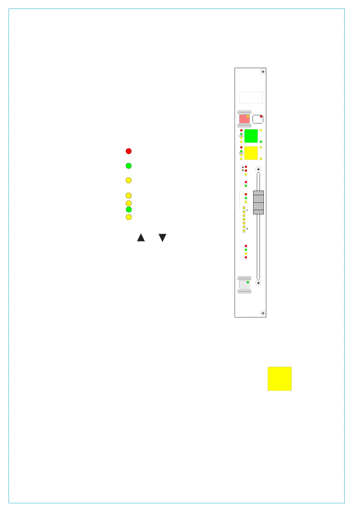
CHANNEL AND gROUP fADERS (STyLE 1)
If your console uses Style 2 faders please
refer to the description in the Fader Area
section of this manual. Style 2 faders
have a different button layout, and are
slightly different, in the way that the
current assignment, interrogated paths
and VCA groups are indicated.
A and B Layering
Each fader can control two independent
audio signal paths, named A and B. These
paths can be either channels or groups.
Both signal paths are fully equipped with
the same facilities.
Assignable Control
The A and B fader assign buttons
are used to select the channel paths.
Selecting a path causes the central
control panels (Assign panels) to display
and control the settings for that fader’s
channel or group path.
Changes made to the Assign panels
will affect the selected path only. When
switching between the paths, the displays,
LEDs and fader position change to match
the settings of each path.
Path Labels
The label in the display is the name
associated with the path’s assigned input,
or the group number if the path is a group.
The input labels default to the Port ID but
can be changed to a more suitable label
using the I/O screens. Path A’s label is
shown in the top half of the display, and
path B’s label is shown in the bottom half
of the display.
If path A is active, the A fader assign
button and the label will be lit in green. If
path B is active, the B fader assign button
and the label will be lit in amber.
Channel or Group Cut/On
The CUT button cuts the channel or
group, its effect is the same as fading it
out completely. There can be ON buttons
here instead, which switch the channel on.
AFL
AFL will be heard in surround through
the monitor loudspeakers (main or small),
if surround panning is in use and the
loudspeaker system is surround.
Indicative LEDs
A set of LEDs next to the assign buttons
give more information about the path.
MR - The fader path is a Master of a
VCA style group
SL - The fader path is a slave within a
VCA style group
ST - The path is a stereo channel or
group
SS - The path is a surround master
GP - A group is assigned to the path
A - Path A is active
B - Path B is active
The and Null LEDs illuminate
when the position of the fader is not
the same as the level of the audio. If a
VCA Master is moved away from the `0’
position, the null leds on the slaves will
light to indicate whether the audio is above
or below the position of the fader.
The T LED indicates that the console
has recognized that the fader has been
touched.
The PEAK LED will illuminate if the
channel or group signal is within 3 dB of
the clipping level.
The ON LED illuminates when the audio
level is not at the
: position.
The EQ, FLTR, DYN and M/S LEDs
indicate that these functions are switched
IN on the selected path (EQ, Filters and
Dynamics settings may be flat).
Fader Bargraph
The fader bargraph indicates the level
at the channel input (post the input gain
and switching and the tone switching),
the channel direct output, or the gain
reduction of the dynamics, indicated by
the three LEDs. Selection is made either
on the Functions panel, or on the USER-
CHAN screen.
PFL
PFL is provided on the
fader overpress and on the
button. It will be heard on
the small LS (or the main LS
if PFL to Mon is selected),
or PFL LS (depending
upon how the monitoring is
configured).
VCA Group
Interrogation
Interrogation provides a
clear way of indicating
VCA group assignments.
Interrogation is performed
by holding down the Assign
button of a VCA group
member, the assign buttons
of all members of the same
group will light.
Interrogation of a Primary
Master will light the Assign
buttons of its primary slaves
and secondary masters.
Interrogation of a
secondary master will light
the Assign buttons of its
secondary slaves, and the
primary master’s Assign
button will flash.
Interrogate Mode - Routing Panel
It is possible to discover which fader paths
are feeding each of the routing busses by
putting the panel into “Interrogate” mode.
This is done by pressing the INTER
button. If any of the routing buttons
(groups, mains, tracks) are held down,
the fader assign buttons of all the paths
feeding that bus will light. This button can
also be used to interrogate mix minus
feeds using the BUS button on the Input/
Output panel.