CALREC Putting Sound in the Picture 111
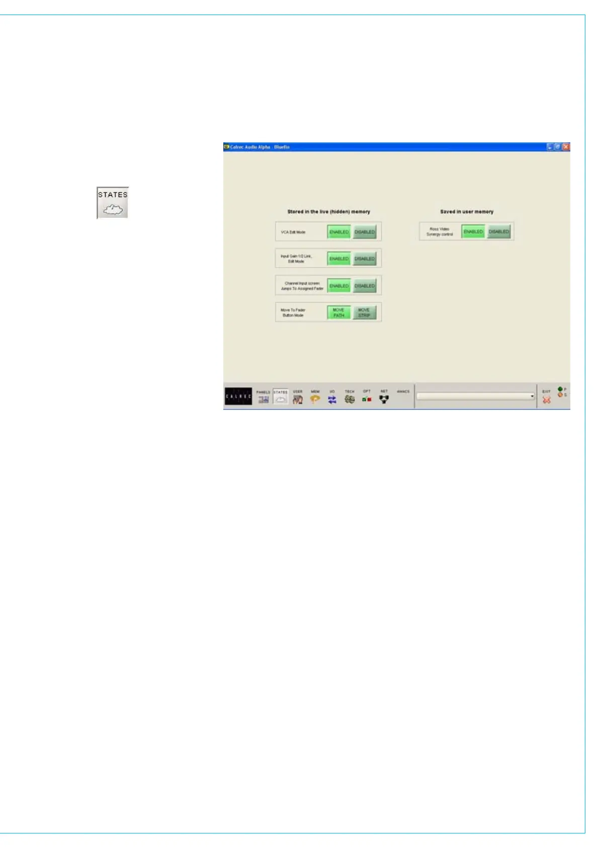
The options are in two groups. Those in
the left column (‘Stored in the live/hidden
memory’) remain are not affected by the
console memory system. The one in the
right column will be changed to whatever
state it had when that memory was saved.
LS Monitor Insert (Only Visible
When Traditional Style Monitor
Panels are Used)
In addition to the monitor panel button, the
LS monitor insert can be switched in and
out on this screen. The send ports are
patched on the I/O - Output - Mon, TB &
Osc screen. The return ports are patched
on the Options - Mon I/P & TB - Mon Sel
(EXT I/P) screen.
PFL Monitor Options (Only Visible
When Traditional Style Monitor
Panels are Used)
PFL TO MON feeds PFL to the Control
Room Loudspeaker outputs (post
surround panning controls), overriding the
LS Selector. PFL to H/P feeds the PFL
signal to the headphones. The APFL
Flash will enable or disable the flashing
of the APFL indicator on the Broadcast
Facilities panel.
VCA Edit mode
Disabling provides protection against
accidental changes to VCA groups.
Input 1 and 2 Gain Linking
Channels have two inputs and the
gains can either be linked, or adjusted
separately.
STATES SCREEN
Channel Inputs Screen
If enabled, selecting a fader assign button
causes the Channel Inputs patching
screen to scroll to that fader in the
patching list.
Move To Fader Button Mode
The Move Path buttons on the I/O Matrix
panel can be set to move the selected
path (A or B) to another fader; or they can
be set to move the entire fader strip (both
paths A and B). In both cases, any Wild
control assignments will also move with
the path.
Ross Video Synergy control
This allows a Ross Synergy 2 or 3
switcher, often under control from a Ross
Overdrive automation system, to control
the following functions:
level of input/group faders
•
fader ON/CUT status•
activate console PFL of those faders•
level of main output faders•