CALREC Putting Sound in the Picture 81
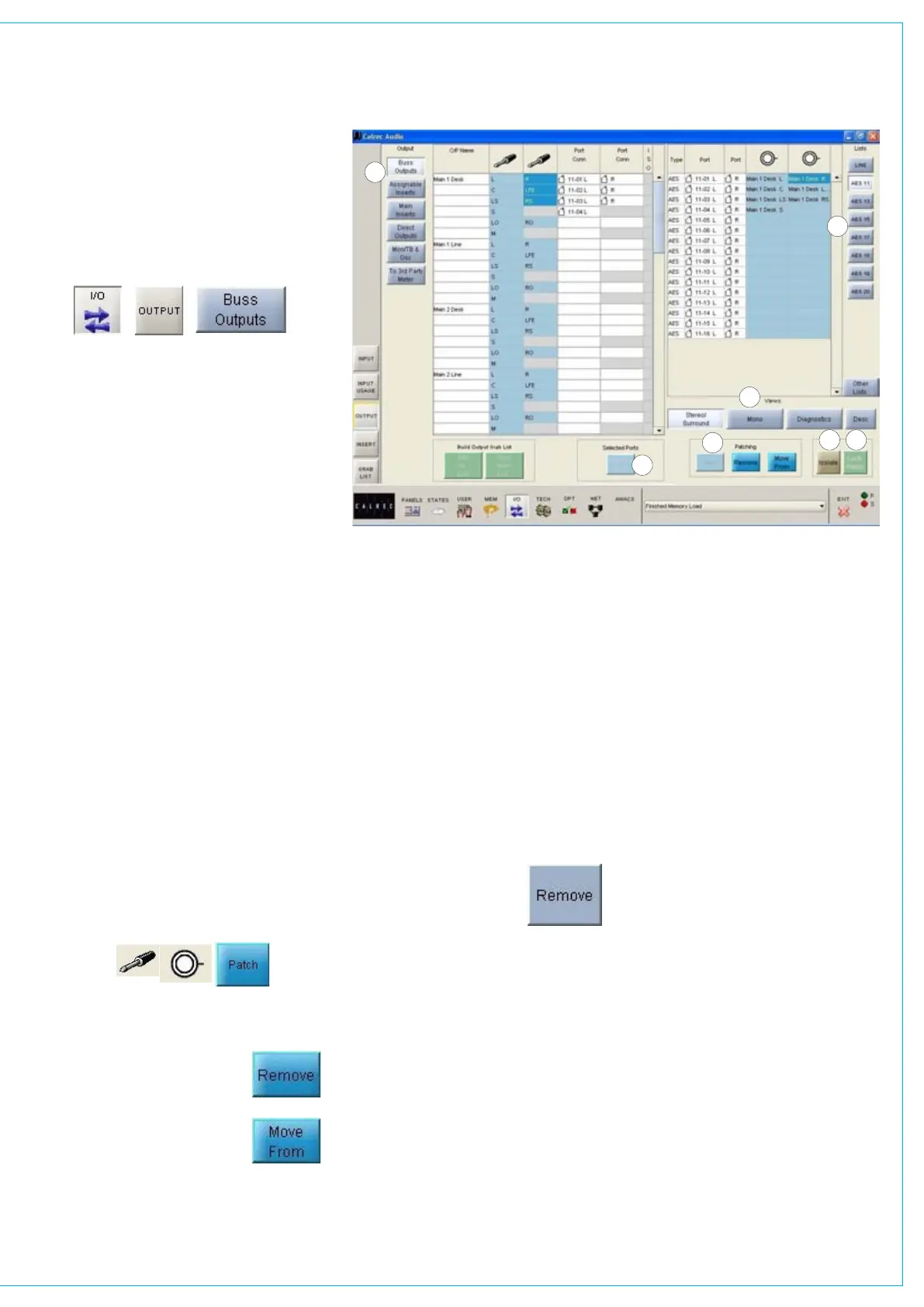
(1) Output Port Lists
All of the available ports can be grouped
into suitable lists using Options - Port
Lists screens. These lists can then be
displayed on the right of this screen, ready
to have signals patched to them from the
left. Different lists are accessed using the
selection buttons.
(2) Viewing Options
The sources can be viewed as pairs (for
patching to stereo or surround paths),
individual (for patching to mono paths),
or individual with the actual rack number,
card slot and input shown (for diagnostic
purposes).
(3) Output Views
These buttons select the different
categories of console output signals
which can be patched to output ports (e.g.
buss outputs, insert sends, direct outputs,
monitoring outputs, Talkback outputs,
oscillator outputs, external meter outputs).
They will then be displayed in the main
section of this screen.
(4) Patching
To make an assignment, select an output
signal, and an output port, and select Patch.
Output signals can be patched to any
number of output ports by repeating this
procedure. (If groups are set to be mono,
only the left output will have a signal on it).
Patches can be removed from
selected output ports using
the REMOVE patching button.
Connections can be moved
between output ports when
selected using the MOVE
FROM button. The Name field will be
highlighted and the PATCH, REMOVE and
OUTPUT PORTS
MOVE FROM buttons will be replaced
with MOVE TO and CANCEL. Upon
selection of a new patch point, pressing
MOVE TO will move the connection.
CANCEL will cancel the operation.
Multiple Patching - It is possible to patch
signals to many outputs in one operation:
Select first source point
•
Select the output ports
• by dragging
down the column, these have to be all
in the same column
Select Patch
•
(5) Remove
The Remove button allows
an output signal to be
removed from its output port
assignment or assignments,
without needing to locate the output port
or ports to which it is patched. Simply
select the port connection from the “Port
Conn” column on the list of output signals,
and select Remove.
(6) Port Isolation
The ISOLATE button allows the selected
port connection to be isolated from
memory recall, so that its current settings
will not be over-written by what is in the
memory. Clicking the button a second
time will de-isolate the connection. A
brown cell in the Label column indicates
that a port has been isolated.
(7) Output Port Locking
Some output ports may need to be
‘locked’ once they have been set up to
avoid accidental removal. For example,
the console’s Main 1 output signal may
be assigned to a particular output port.
If this were the main studio transmitter
output, it would be very undesirable
to allow the assignment to be easily
changed during normal operation.
For this reason, a locking system is
provided to protect critical parts of each
configuration.
Operation of the locking system is only
available in “Technician” or “Supervisor”
mode which are password protected to
add an extra layer of security. Modes
are selected using the TECH - User
Mode screen.
To lock an output port assignment,
select an output port which has a
source assigned to it, and select the
LOCK PATCH button. Provided that
the desk is in “Technician” mode, the
lock state will be toggled.
If the lock is active, the port name will be
highlighted in bright green text.
Once a patch has been locked, any
attempt to patch over it, move it, or
remove it will display the error message:
“Patch locked!”
1
6
7
4
3
2
5