Chery Automobile Co., Ltd.
39 - AUDIO SYSTEM
39–17
39
Rear Woofer Assembly
Removal
HINT:
Use the same procedures for the right side and left side.
Procedures listed below are for the left side.
1. Turn off all the electrical equipment and ignition switch.
2. Disconnect the negative battery cable.
3. Remove the rear left door protector assembly (See page 47-36).
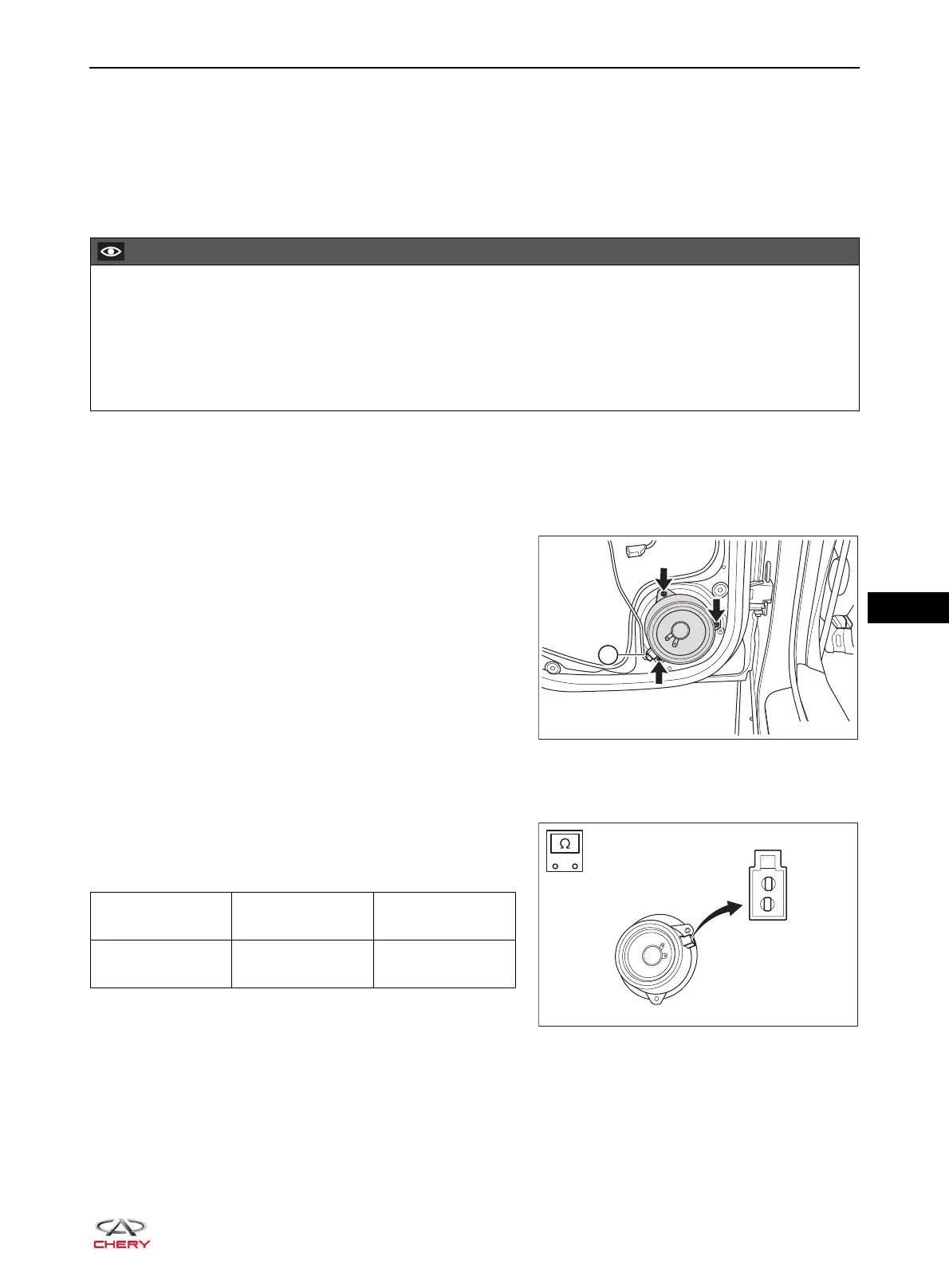
4. Remove the rear left woofer assembly.
a. Disconnect the rear woofer connector (1).
b. Remove 3 fixing screws (arrow) from rear woofer
assembly, and then remove the rear woofer assembly.
(Tightening torque: 2.5 ± 0.5 N·m)
Inspection
1. Check rear woofer assembly.
a. Using a digital multimeter, measure resistance of rear
woofer assembly according to the table below.
Standard Resistance
If result is not as specified, replace the rear woofer
assembly.
2. Check cone paper of rear woofer assembly for damage or deformation. Replace if necessary.
3. Check rear woofer connector for damage and terminals for bend or poor connection. Replace if necessary.
Be sure to wear safety equipment to prevent accidents when removing rear woofer assembly.
Appropriate force should be applied when removing rear woofer assembly. Be careful not to operate
roughly.
Never touch the cone paper and other components of rear woofer assembly during removal; otherwise it
will affect sound effect or damage rear woofer assembly.
Multimeter
Connection
Condition
Specified
Condition
Ter mi n a l 1 -
Ter mi na l 2
Always
Approximately
3.6 Ω