Chery Automobile Co., Ltd.
14 - SQR484F IGNITION SYSTEM
14–9
14
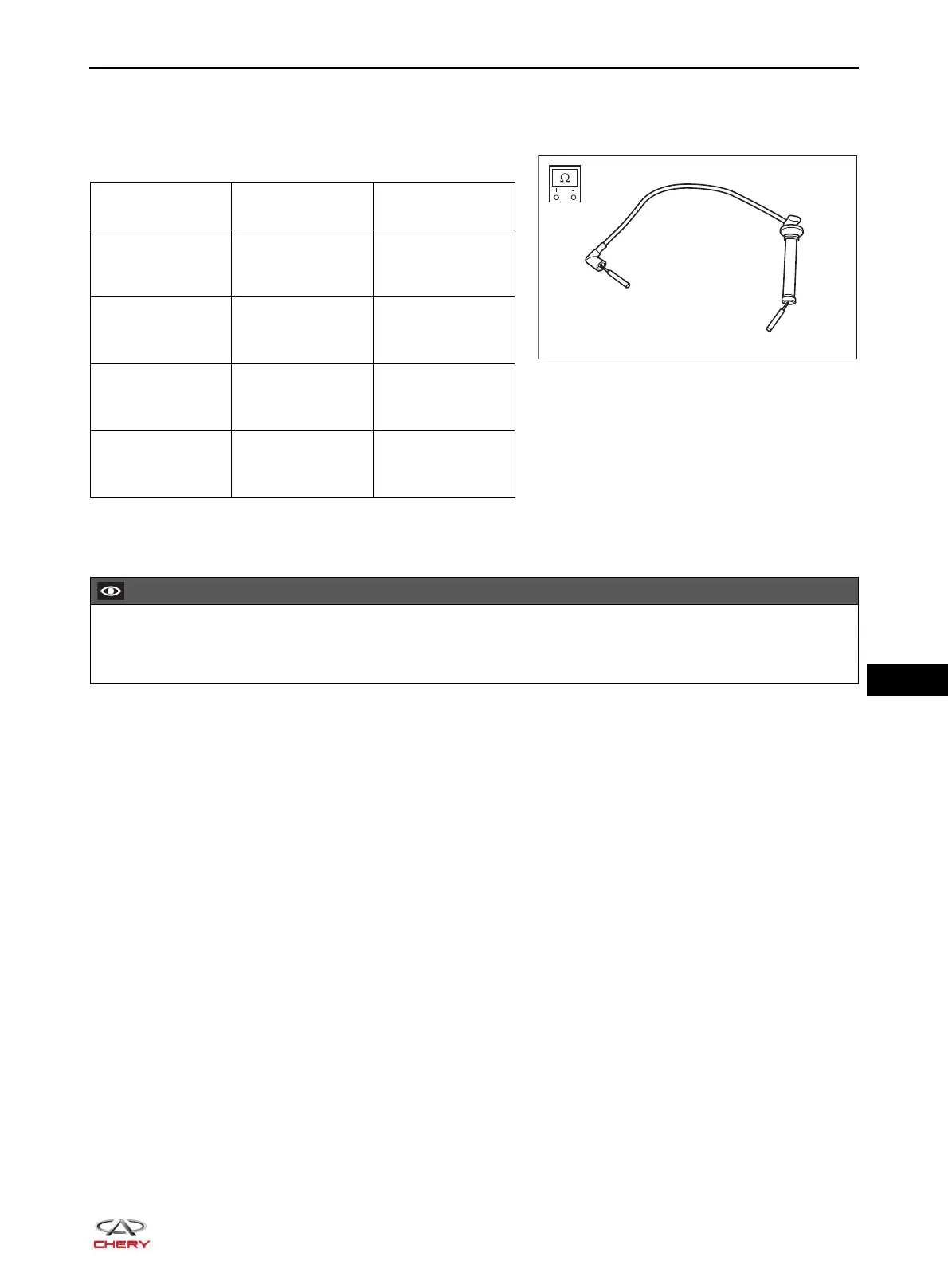
Inspection
Turn digital multimeter to ohm band, and measure resistance of high-voltage cables in the method shown in
the illustration.
If result is not as specified, replace the high-voltage cables.
Installation
Installation is in the reverse order of removal.
Measurement
Item
Condition
Specification
(kΩ)
Cylinder 1
High-voltage
Cable
Normal
temperature
7.5 - 11.2
Cylinder 2
High-voltage
Cable
Normal
temperature
5.8 - 8.3
Cylinder 3
High-voltage
Cable
Normal
temperature
4.2 - 6.7
Cylinder 4
High-voltage
Cable
Normal
temperature
4 - 6.5
Install cylinder 1 to 4 high-voltage cables to spark plug hole and ignition coil in accordance with the
marks on high-voltage cables.