Chery Automobile Co., Ltd.
07 - SQR484F ENGINE MECHANICAL
07–29
07
Removal
1. Turn off all the electrical equipment and ignition switch.
2. Disconnect the negative battery cable.
3. Remove the engine trim cover assembly (See page 10-10).
4. Remove the engine lower right protector assembly (See page 48-29).
5. Remove the accessory drive belt (See page 07-24).
6. Remove the belt tensioner assembly (See page 07-27).
7. Use an engine equalizer to hang the engine right lifting eye.
8. Remove the engine right mounting (See page 07-68).
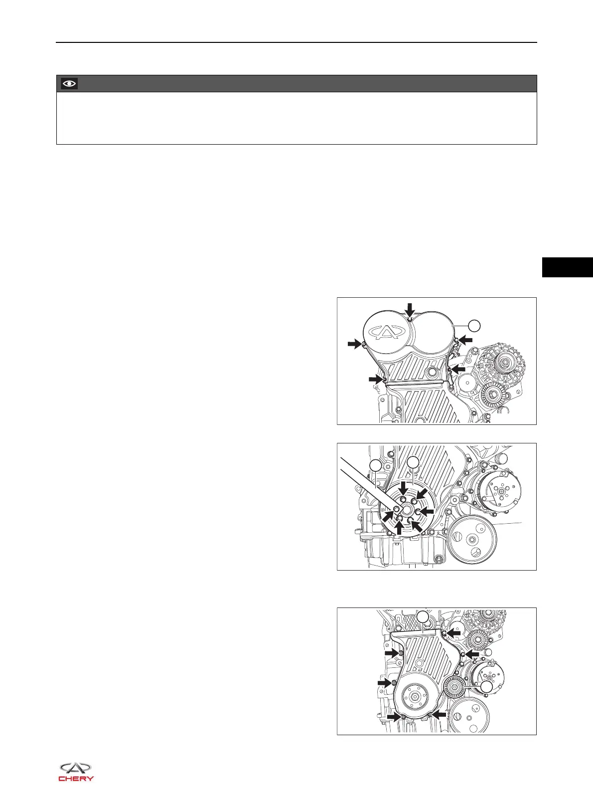
9. Remove the timing belt front cover.
a. Loosen and remove 5 fixing bolts (arrow) from timing
belt front cover upper body, and remove the timing
belt front cover upper body (1).
(Tightening torque: 7 N·m)
b. Loosen and remove 6 fixing bolts (arrow) from
crankshaft pulley, and remove the crankshaft pulley
(1).
(Tightening torque: 1st step: tighten to 25 ± 5 N·m;
2nd step: retighten by 30° ± 5°)
HINT:
Shift the transmission into 5th gear (for MT model) or
D position (for CVT model) when loosening the
crankshaft timing gear fixing bolt to engage the
crankshaft and propeller shaft. Another technician
depresses the brake pedal, which can lock the
crankshaft by mechanical gear train.
c. Loosen and remove the fixing bolt from accessory
drive belt lower idler pulley assembly, and remove the
accessory drive belt lower idler pulley assembly (1).
(Tightening torque: 40 + 5 N·m)
d. Loosen and remove 6 fixing bolts (arrow) from timing
belt front cover lower body, and remove the timing belt
front cover lower body (2).
(Tightening torque: 7 N·m)
Be sure to wear necessary safety equipment to prevent accidents when repairing.
Try to prevent body paint surface from being scratched during removal and installation.
RT21070080
1
RT21070090
2
1
RT21070100
2
1
 Loading...