Chery Automobile Co., Ltd.
07 - SQR484F ENGINE MECHANICAL
07–68
07
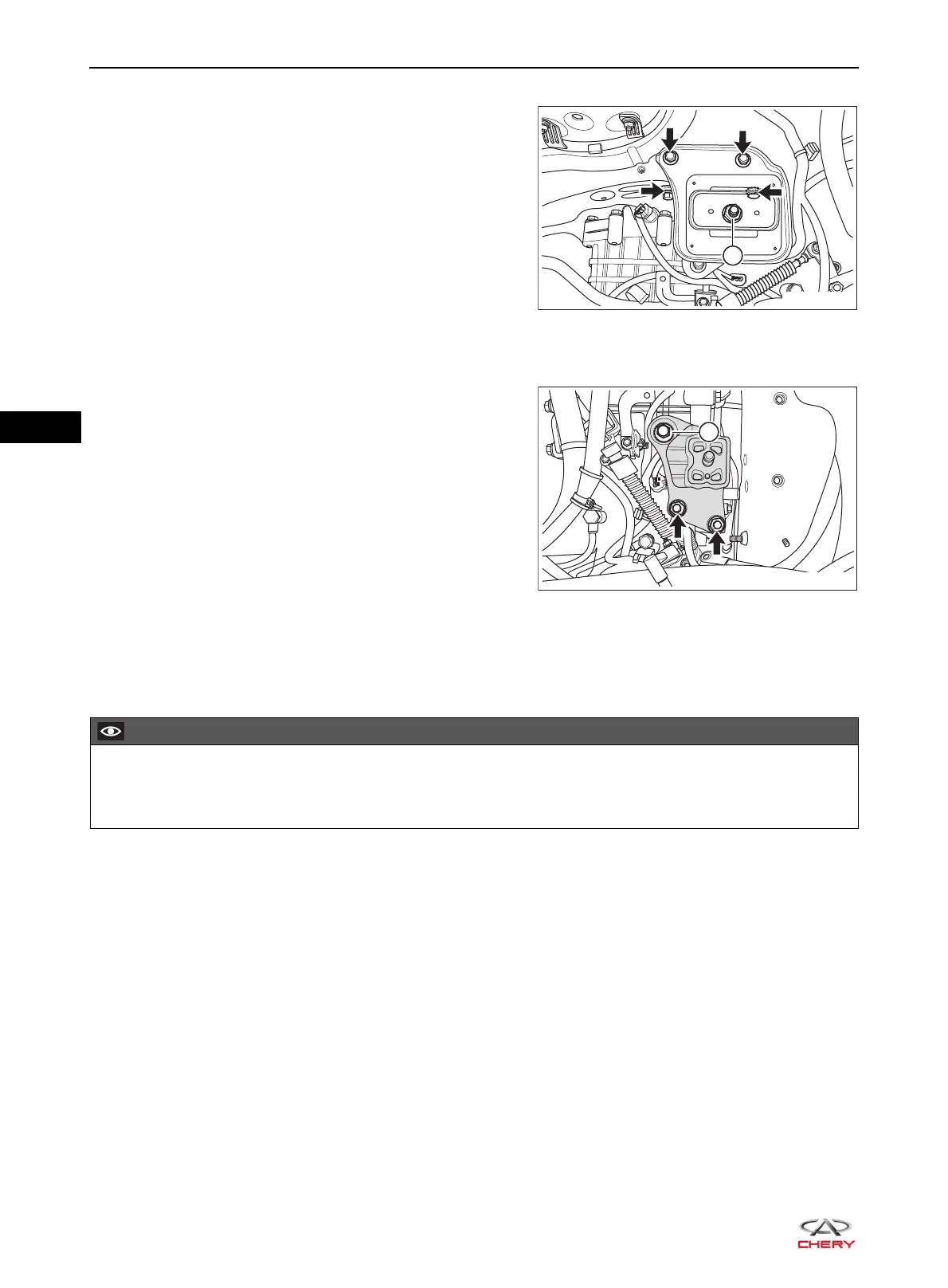
9. Remove the engine left mounting cushion assembly (for CVT model).
a. Remove the locking nut (1) from left mounting cushion
assembly.
(Tightening torque: 80 ± 6 N·m)
b. Remove 4 coupling bolts (arrow) between left
mounting cushion assembly and body.
(Tightening torque: 70 ± 5 N·m)
c. Remove the left mounting cushion assembly.
10.Remove the engine left mounting bracket (for CVT model).
a. Remove 2 fixing nuts (arrow) between left mounting
bracket and transmission case.
(Tightening torque: 80 ± 6 N·m)
b. Remove the coupling bolt (1) between left mounting
bracket and transmission case.
(Tightening torque: 80 ± 6 N·m)
c. Remove the left mounting bracket.
11.Installation is in the reverse order of removal.
Removal & Installation - Right Mounting Assembly
1. Turn off all the electrical equipment and ignition switch.
2. Disconnect the negative battery cable.
3. Remove the engine trim cover assembly (See page 10-10).
4. Remove the engine lower right protector assembly (See page 48-29).
5. Use an engine equalizer to hang the engine.
6. Remove the engine right mounting cushion assembly.
Be sure to wear necessary safety equipment when repairing to prevent accidents.
Try to prevent body paint surface from being scratched during removal and installation.
 Loading...