12-6
Cisco ASR 1000 Series Aggregation Services Routers SIP and SPA Software Configuration Guide
OL-14127-08
Chapter 12 Overview of the POS SPAs
SPA Architecture
SPA Architecture
This section provides an overview of the architecture of the POS SPAs and describes the path of a packet
in the ingress and egress directions. Some of these areas of the architecture are referenced in the SPA
software and can be helpful to understand when troubleshooting or interpreting some of the SPA CLI
and show command output.
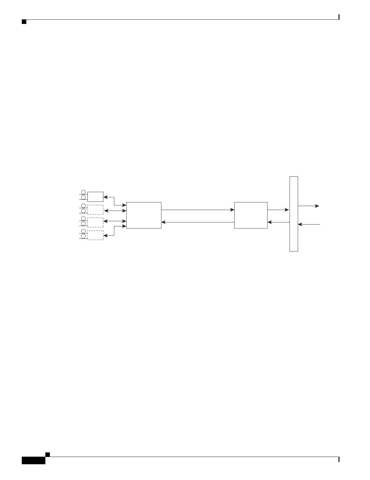
4-Port OC-3c/STM-1 POS SPA Architecture
Figure 12-1 identifies some of the hardware devices that are part of the POS SPA architecture. The figure
shows the four ports that are supported by the 4-Port OC-3c/STM-1 POS SPA only.
Figure 12-1 4-Port OC-3c/STM-1 POS SPA Architecture
Every incoming and outgoing packet on the 4-Port OC-3c/STM-1 POS SPA goes through the
SONET/SDH framer and field-programmable gate array (FPGA) devices.
Path of a Packet in the Ingress Direction
The following steps describe the path of an ingress packet through the 4-Port OC-3c/STM-1 POS SPA:
1. The framer receives SONET/SDH streams from the SFP optics, extracts clocking and data, and
processes the section, line, and path overhead.
2. The framer extracts the POS frame payload and verifies the frame size and frame check sequence
(FCS).
3. The framer passes valid frames to the field-programmable gate array (FPGA) on the SPA.
4. The FPGA on the SPA transfers frames to the host through the SPI4.2 bus for further processing and
switching.
Path of a Packet in the Egress Direction
The following steps describe the path of an egress packet through the 4-Port OC-3c/STM-1 POS SPA:
1. The host sends packets to the FPGA on the SPA using the SPI4.2 bus.
2. The FPGA on the SPA stores the data in the appropriate channel first-in first-out (FIFO) queue.
3. The FPGA on the SPA passes the packet to the framer.
Optics
SONET/SDH
Streams
Packets
SONET/SDH
Framer
FPGA
Packets
SPA
Connector
To
Host
From
129281

 Loading...


