Product Manual — Doc. 9045M DM NAX® • 103
Balanced/Unbalanced Audio Input
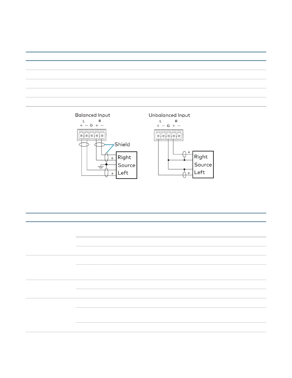
Refer to the following table and illustration for analog audio input pin assignments and connection
information.
Signal Name Balanced Audio Input Unbalanced Audio Input
+ L+ L+
- L− Open
G Shield/ground Open
+ R+ R+
- R- Open
Observe the LED Indicators
Refer to the following table for information about the LED indicators on the device.
LED Indicator Color Meaning
PWR Amber Power is being applied to the device. Thedevice is
booting.
White Device is powered on with audio passing.
Red Device is in standby mode.
LAN White The device is powered on and has a valid IP address.
Off Device is not connected to a network or the IP address is
invalid.
NAX White AoIP is ready to pass and the unit's PTP clock is synced.
Off No AoIP is passing to or from and/or PTP is not synced.
SOURCE 1-16 White Signal is detected on the specified input/source.
Red There is clipping on an analog input or bitstream audio
detected on a digital input.
Off There is no signal detected on the specified input/source.

 Loading...