173 • DM NAX® Product Manual — Doc. 9045M
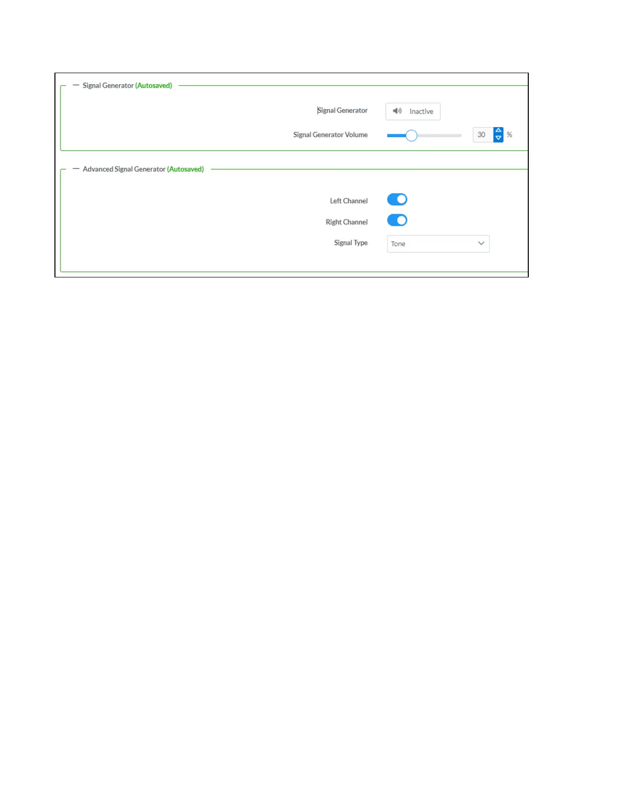
Signal Generator
The DM-NAX-2XLRI-1G has a built-in signal generator that allows an integrator to send an audio signal
to the output for testing purposes.
1. To route the signal generator to the zone output, click the Signal Generator button so that it
displays Active and is highlighted in blue. To unroute the signal generator on the zone output, click
the Signal Generator button so that it displays Inactive and is highlighted in grey. By default, the
signal generator is not routed to the zone output.
2. To adjust the signal generator's volume, do one of the following:
l
Move the Signal Generator Volume slider right to increase or left to decrease the volume.
l
Click the arrows to increase or decrease the signal generator volume. Values range from 0
to 100, adjustable in increments of 1.
l
Manually enter a value in the Signal Generator Volume field.
Advanced Signal Generator
The advanced signal generator settings control the signal type of the signal generator, and allow the left
and right channel to be enabled or disabled independently of one another.
1. Set the Left Channel toggle to the right position to enable the left channel of the signal. Set the
toggle to the left position to disable the left channel. By default, Left Channel is enabled.
2. Set the Right Channel toggle to the right position to enable the right channel of the signal. Set the
toggle to the left position to disable the right channel. By default, Right Channel is enabled.
3. Select an audio test signal type from the Signal Type drop-down menu. The available signal types
are:
l
Tone: Generates a 1kHz sine wave tone.
l
Pink Noise: Generates pink noise.
l
White Noise: Generates white noise.
Click Done to return to the Settings tab of the web user interface.

 Loading...